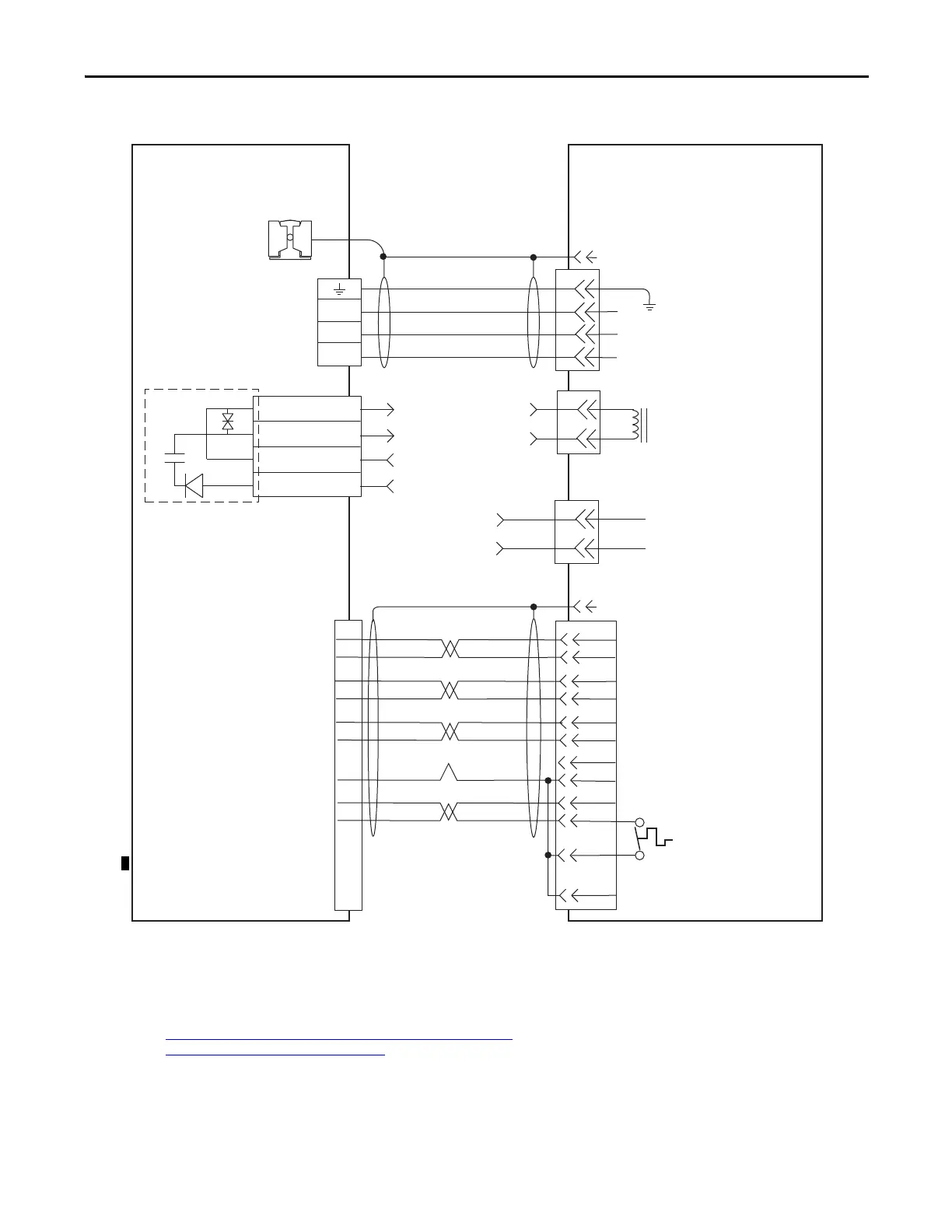
Motor Power
(MP) Connector
Motor Feedback
(MF) Connector
Motor Feedback
Thermostat
Motor Power Cable
(customer-supplied)
2090-CFBM7DF-CEAAxx, or
2090-XXNFMF-Sxx (standard, non-flex)
or
2090-CFBM7DF-CEAFxx, or
CFBM4DF-CDAFxx (continuous-flex)
Cable Shield
Clamp
Spring-set Brake
(Single-phase)
Customer-supplied
Interface to
460V AC Power
Customer-supplied
24V DC
(1)
HPK-B/Exxxx
460V High-power Servo Motors with
Absolute Encoder
Kinetix 7000 Drive
Motor Connector Shell
Motor Connector Shell
Motor Power (Three-phase)
Cable shield clamp must be used to
meet CE and UK requirements. No
external connection to ground
required.
(1) See Customer-supplied 24V DC Power Supply Notes (Kinetix HPK motors) on page 176 for important wiring information.
(2) See Kinetix HPK
Motor Blower Connections on page 176 for more information.
Blower Connections
(2)
2090-K6CK-D15M connector
kit

 Loading...


