98 Rockwell Automation Publication 2099-UM001G-EN-P - December 2022
Chapter 4 Connect the Kinetix 7000 Drive System
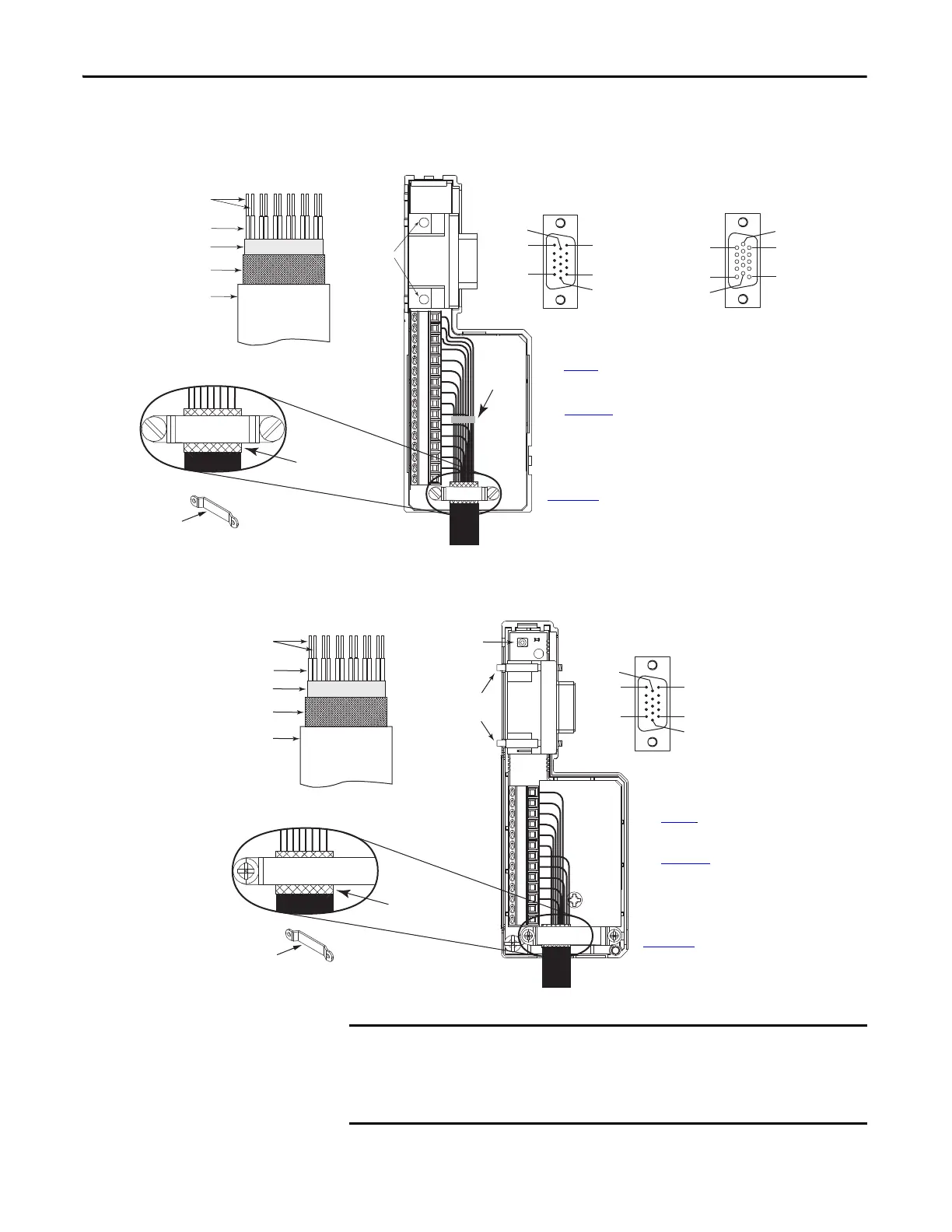
Figure 57 - Wiring (15-pin) Flying-lead Feedback Cable Connections
2090-K6CK-D15M and 2090-K6CK-D15F Connector Kits
Figure 58 - Wiring (15-pin) Flying-lead Feedback Cable Connections
2090-K7CK-KENDAT Feedback Module
Pin 1
Pin 11
Pin 10
Pin 5
Pin 6
Pin 15
Pin 1
Pin 10
Pin 5
Pin 11
Pin 6
Pin 15
1
2
34
5
678
91011121314150
15-pin (male) Motor Feedback
Low-profile Connector
15-pin (female) Auxiliary Feedback
Low-profile Connector
See page 64
for Feedback Signal Descriptions.
See Appendix
B for the Motor Feedback
Interconnect Drawing for Your Application.
Tie
Wrap
Exposed Braid Under Clamp
Kinetix 2090 Feedback Cable
Shield Clamp
Outer insulation
Braided shield
Foil shield
Wire insulation
Bare wires
Kinetix 2090
Feedback Cable
Turn Clamp Over to Hold
Small Wires Secure
Mounting
Screws
See the Low Profile Connector Kit Installation
Instructions, Publication
2094-IN007
, for Connector Kit Specifications.
2090-K6CK-D15x
Low-profile Connector Kit
Pin 1
Pin 10
Pin 5
Pin 11
Pin 6
Pin 15
678
910111213
1
2
34
5
15-pin (male) Motor Feedback
Low-profile Connector
See page 64
for Feedback Signal
Descriptions.
Exposed Braid Under Clamp
Shield Clamp
Outer Insulation
Braided Shield
Foil Shield
Wire Insulation
Bare Wires
Turn Clamp Over to Hold
Small Wires Secure.
Mounting
Screws
See Appendix
B for the Motor Feedback
Interconnect Drawing for Your Application.
2090-K7CK-KENDAT
Low-profile Feedback Module
Kinetix 2090
Feedback Cable
Kinetix 2090
Feedback Cable
Status
Indicator
See the Low Profile Connector Kit Installation
Instructions, Publication
2094-IN007
, for Connector Lit Specifications.
The purpose of the cable shield clamp is to provide a proper ground and
improve system performance, not stress relief.
Clamping the exposed braid under the shield clamp is critical. Turn the
clamp over, if necessary, to be sure of a proper ground.

 Loading...


