Rockwell Automation Publication 750-TG100B-EN-P - June 2019 131
Frame 7 Components Chapter 6
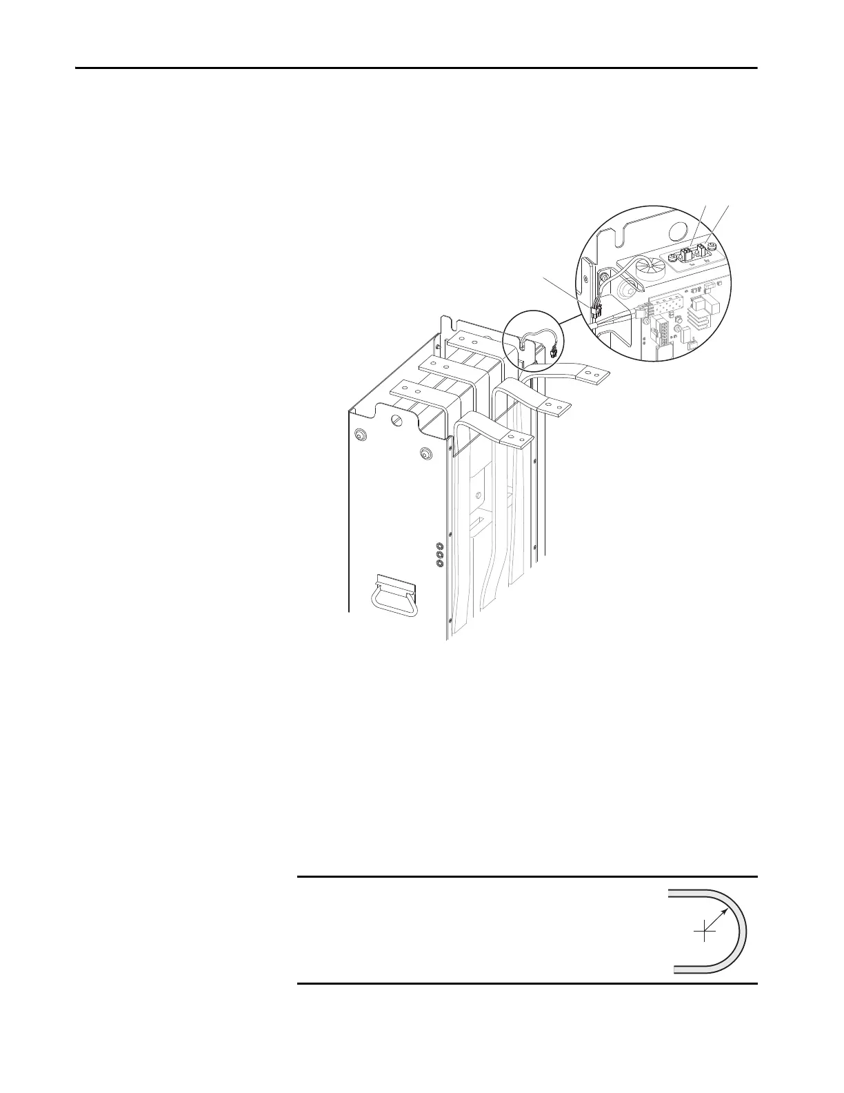
15. Disconnect the AC fuse wire harness connector P1 from connector J1 on
the LCL filter I/O panel.
16. Disconnect the 240V AC power wire harness connector P2 from J2 on the
LCL filter module I/O panel.
17. Remove the LCL filter module from the enclosure.
Install the LCL Filter Module in the Enclosure
Install the LCL filter module into the enclosure in the reverse order of removal.
When installing the fiber-optic cables:
1. Remove the transceiver from the fiber-optic port on the power layer
interface circuit board.
IMPORTANT
Minimum inside bend radius for fiber-optic cable is 50 mm
(2 in.). Any bends with a shorter inside radius can
permanently damage the fiber-optic cable. Signal
attenuation increases as inside bend radius is decreased.

 Loading...


