Rockwell Automation Publication 750-TG100B-EN-P - June 2019 75
Chapter 5
Frame 6 Components
This chapter provides detailed instructions for how to remove and replace
frame 6 PowerFlex® 755T product components.
Frame 6 Kits
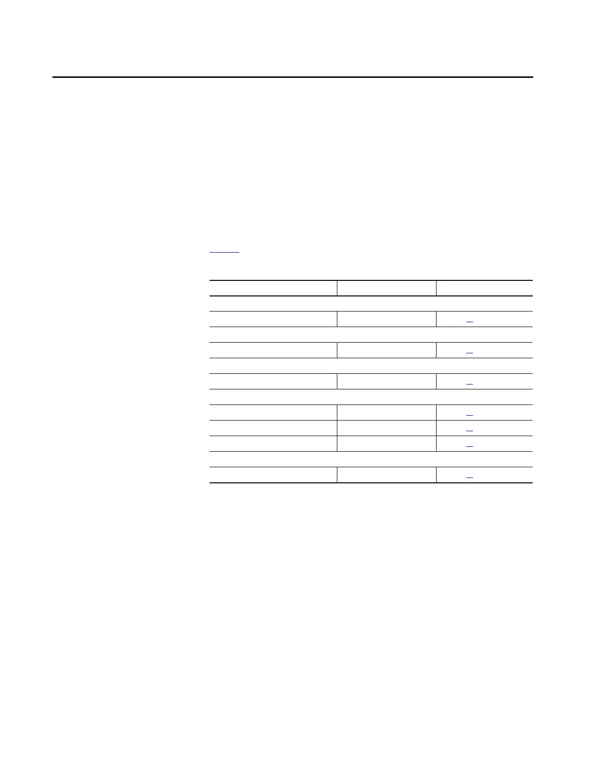
Tab le 9 lists the replacement kits available for frame 6 PowerFlex 755T products.
Table 9 - Frame 6 Replacement Kits
Description Catalog Number Replacement Instructions
Power Module Components
Power Feedback Board and Bracket SK-RM-PFB-F5-F6 See page 87
LCL Filter Module Components
Capacitor
(1)
(1) 480V 6 A drives have one capacitor. All other drive and bus supply power ratings have two capacitors. You must order two kits to
replace both capacitors, where applicable.
SK-RM-LCLCP4-F6 (400/480V) See page 91
Control Pod Components
Main Control Circuit Board SK-RM-MCB1-PF755 See page 77
Cooling Components
Stirring Fan Assembly SK-RM-MFAN1-F6 See page 81
Heatsink Fan Assembly SK-RM-HSFAN1-F6 See page 82
Fan Power Supply Circuit Board SK-RM-PSB1-F5-F6 See page 84
Accessories Kits
DR and PE-A (EMC & MOV) Jumper SK-RM-JMPR1-F6 See page 83

 Loading...


