190 Rockwell Automation Publication 750-TG100B-EN-P - June 2019
Chapter 8 Input Bay Components
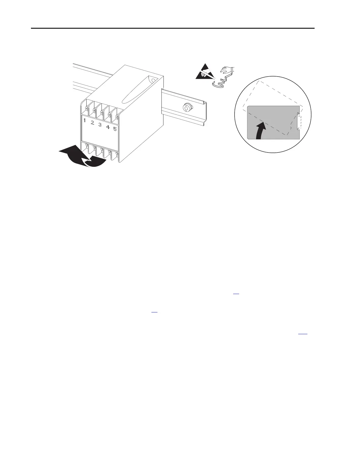
6. Pull up on the bottom of the relay chassis and lift it up and off the DIN
rail.
Install the AC Precharge Time Delay Relay
Install the AC precharge time delay relay in the reverse order of removal.
AC Precharge TVSS Module
Replacement
Replace the AC precharge TVSS module with kit catalog number
20-750-MACP-xx-TVSS.
Remove the AC Precharge TVSS Module
Follow these steps to remove and replace the AC precharge TVSS module.
1. Review the Product Advisories on page 14
.
2. Remove power from the system. See Remove Power from the System on
page 15
.
3. Open the input bay enclosure door.
4. Remove the guard from the enclosure. See Guard Removal on page 183
.
5. Disconnect connector P15 from the module.
6. Remove the torx screw or hex nut that secures the ground wire to the
appropriate PE-A1 terminal.

 Loading...


