144 Rockwell Automation Publication 750-TG100B-EN-P - June 2019
Chapter 7 Control Bay and Control Pod Components
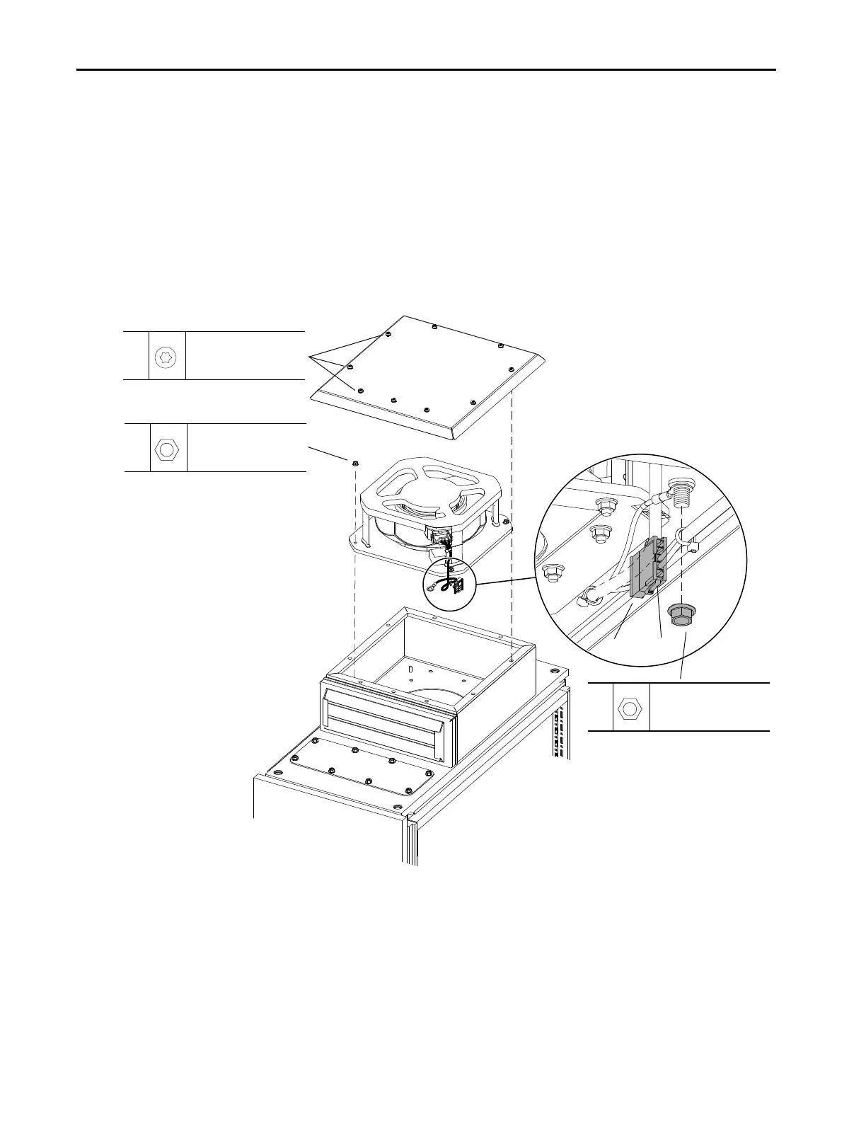
4. Disconnect the fan P2 connector from connector P12 on the inside of the
enclosure.
5. Remove the M8 hex nut and washer that secure the ground wire to the
inside of the enclosure roof and remove the wire.
6. Remove the nine M4 x 10 mm slotted-torx screws that secure the vent
cover to the top of the vent assembly and remove the cover.
7. Remove the four M4 hex nuts that secure the fan assembly to the vent.
8. Lift the side of the fan opposite from the connector and, while holding the
fan at an angle to the housing, remove the fan.
Install the IP21/IP54 Roof Vent Fan
Install the IP21/IP54 roof vent fan in the reverse order of removal.
6
M4 x 10 mm
T20 or F - 6.4 mm (0.25 in.)
2.6 N
•m (23 lb•in)
7
M4
7 mm
2.6 N
•m (23 lb•in)
P12
5
M8
13 mm
2.6 N
•m (23 lb•in)
P2

 Loading...


