EasyManuals Logo

Rockwell Automation Allen-Bradley PowerFlex 750 Series Service Manual

Rockwell Automation Allen-Bradley PowerFlex 750 Series
352 pages
To Next Page IconTo Next Page
To Previous Page IconTo Previous Page
Page #196 background imageLoading...
Page #196 background image
196 Rockwell Automation Publication 750-TG100B-EN-P - June 2019
Chapter 8 Input Bay Components
2. Remove power from the system. See Remove Power from the System on
page 15
.
3. Open the input bay enclosure door.
4. Remove the guard from the enclosure. See Guard Removal on page 183
.
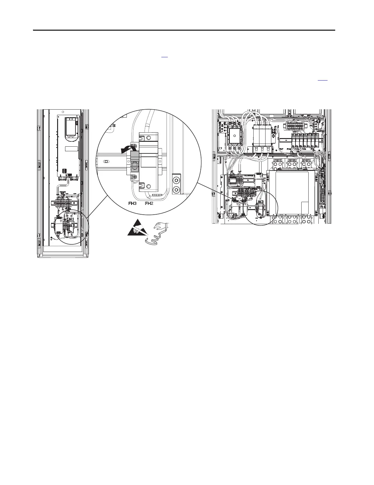
5. Pull out on the tab on the fuse holder and remove the fuse.
Install the Roof Fan 240V Control Power Fuse
Install the roof fan 240V control power fuse in the reverse order of removal.
Control Bay Frame 10 Input Bay
=

Table of Contents

Other manuals for Rockwell Automation Allen-Bradley PowerFlex 750 Series

Questions and Answers:

Question and Answer IconNeed help?

Do you have a question about the Rockwell Automation Allen-Bradley PowerFlex 750 Series and is the answer not in the manual?

Rockwell Automation Allen-Bradley PowerFlex 750 Series Specifications

General IconGeneral
BrandRockwell Automation
ModelAllen-Bradley PowerFlex 750 Series
CategoryDC Drives
LanguageEnglish

Related product manuals