EasyManuals Logo

Rockwell Automation Allen-Bradley PowerFlex 750 Series Service Manual

Rockwell Automation Allen-Bradley PowerFlex 750 Series
352 pages
To Next Page IconTo Next Page
To Previous Page IconTo Previous Page
Page #65 background imageLoading...
Page #65 background image
Rockwell Automation Publication 750-TG100B-EN-P - June 2019 65
Frame 5 Components Chapter 4
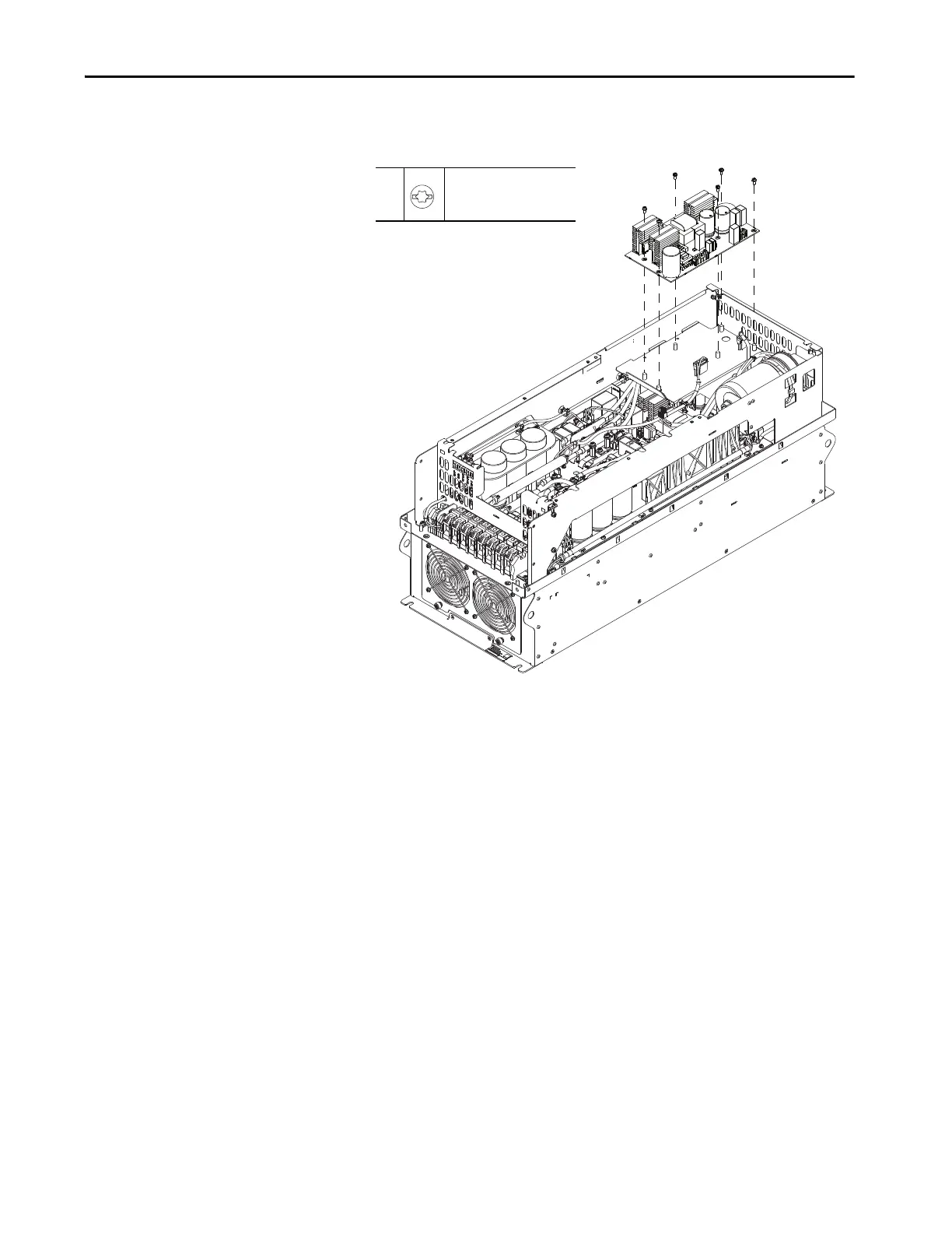
5. Remove the six M4 x 10 mm torx screws that secure the fan power supply
circuit board to the bracket and remove the board.
Install the Fan Power Supply Circuit Board
Install the fan power supply circuit board in the reverse order of removal.
5
M4 x 10 mm
T20
2.0 N•m (18.0 lb•in)

Table of Contents

Other manuals for Rockwell Automation Allen-Bradley PowerFlex 750 Series

Questions and Answers:

Question and Answer IconNeed help?

Do you have a question about the Rockwell Automation Allen-Bradley PowerFlex 750 Series and is the answer not in the manual?

Rockwell Automation Allen-Bradley PowerFlex 750 Series Specifications

General IconGeneral
BrandRockwell Automation
ModelAllen-Bradley PowerFlex 750 Series
CategoryDC Drives
LanguageEnglish

Related product manuals