62 Rockwell Automation Publication 750-TG100B-EN-P - June 2019
Chapter 4 Frame 5 Components
Install the Stirring Fan Assembly
Install the stirring fan assembly in the reverse order of removal. Verify that you
have connected the stirring fan power supply harness connector on the fan
assembly to the connector in the control pod support bracket.
Heatsink Fan Assembly
Replacement
Replace a heatsink fan assembly with kit catalog number SK-RM-HSFAN1-F5.
Remove the Heatsink Fan Assembly
Follow these steps to remove the heatsink fan assembly.
1. Review the Product Advisories on page 14
.
2. Remove power from the system. See Remove Power from the System on
page 15
.
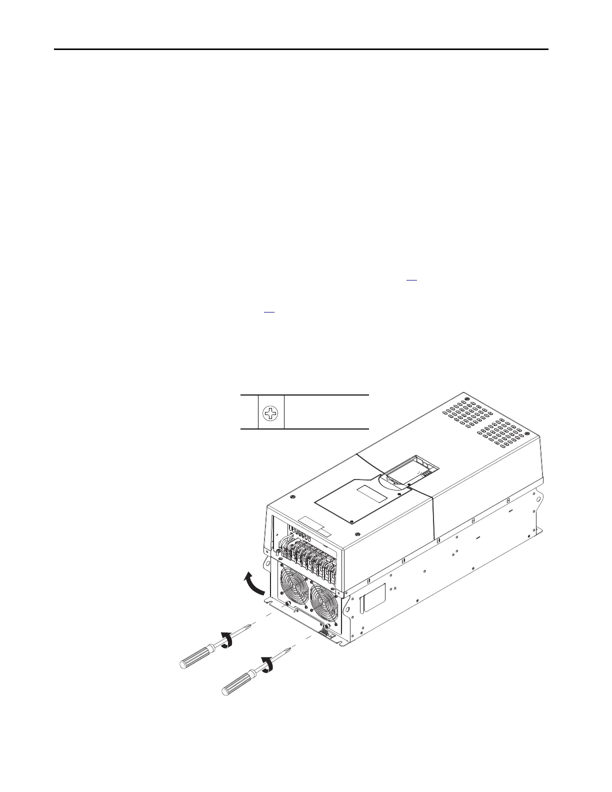
3. Loosen the two captive screws that secure the fan assembly to the chassis.
4. Carefully pull the bottom of the fan assembly away from the chassis and
release the three tabs from the chassis. The power wire harness is
connected inside the chassis.

 Loading...


