108 Rockwell Automation Publication 750-TG100B-EN-P - June 2019
Chapter 6 Frame 7 Components
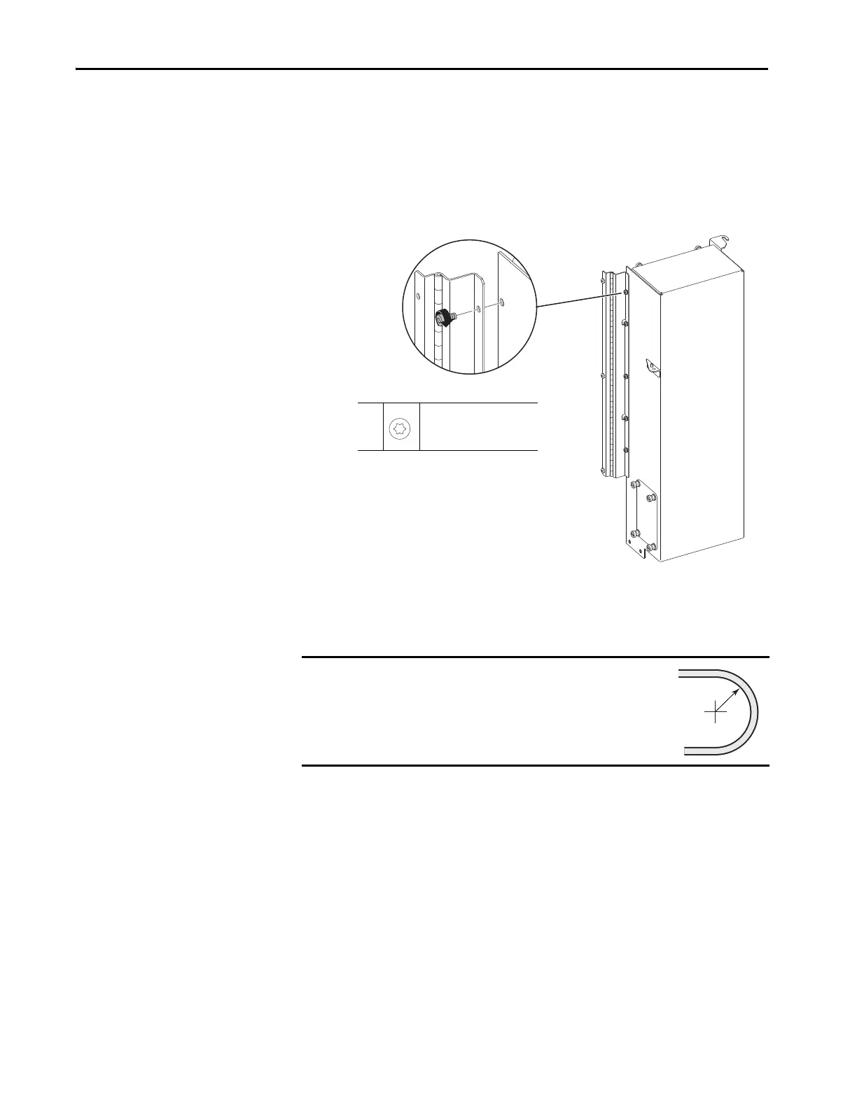
Install the Control Pod Assembly
Install the control pod assembly.
1. Install the hinged mounting bracket on the control pod assembly by using
the five M5 x 12 mm torx screws provided with the kit.
2. Install the control pod assembly in the reverse order of removal.
3. When installing the fiber-optic cables:
a. Without bending the cable to a radius less than 50 mm (2 in.), fully
insert the fiber-optic cable into the transceiver.
b. Insert the transceiver and fiber-optic cable into the connector on the
board, until you hear an audible ‘click.’
IMPORTANT
Minimum inside bend radius for fiber-optic cable is 50 mm
(2 in.). Any bends with a shorter inside radius can
permanently damage the fiber-optic cable. Signal
attenuation increases as inside bend radius is decreased.
1
M5 x 12 mm
T25
6 N•m (53 lb•in)

 Loading...


