EasyManuals Logo

Rockwell Automation Allen-Bradley PowerFlex 750 Series Service Manual

Rockwell Automation Allen-Bradley PowerFlex 750 Series
352 pages
To Next Page IconTo Next Page
To Previous Page IconTo Previous Page
Page #107 background imageLoading...
Page #107 background image
Rockwell Automation Publication 750-TG100B-EN-P - June 2019 107
Frame 7 Components Chapter 6
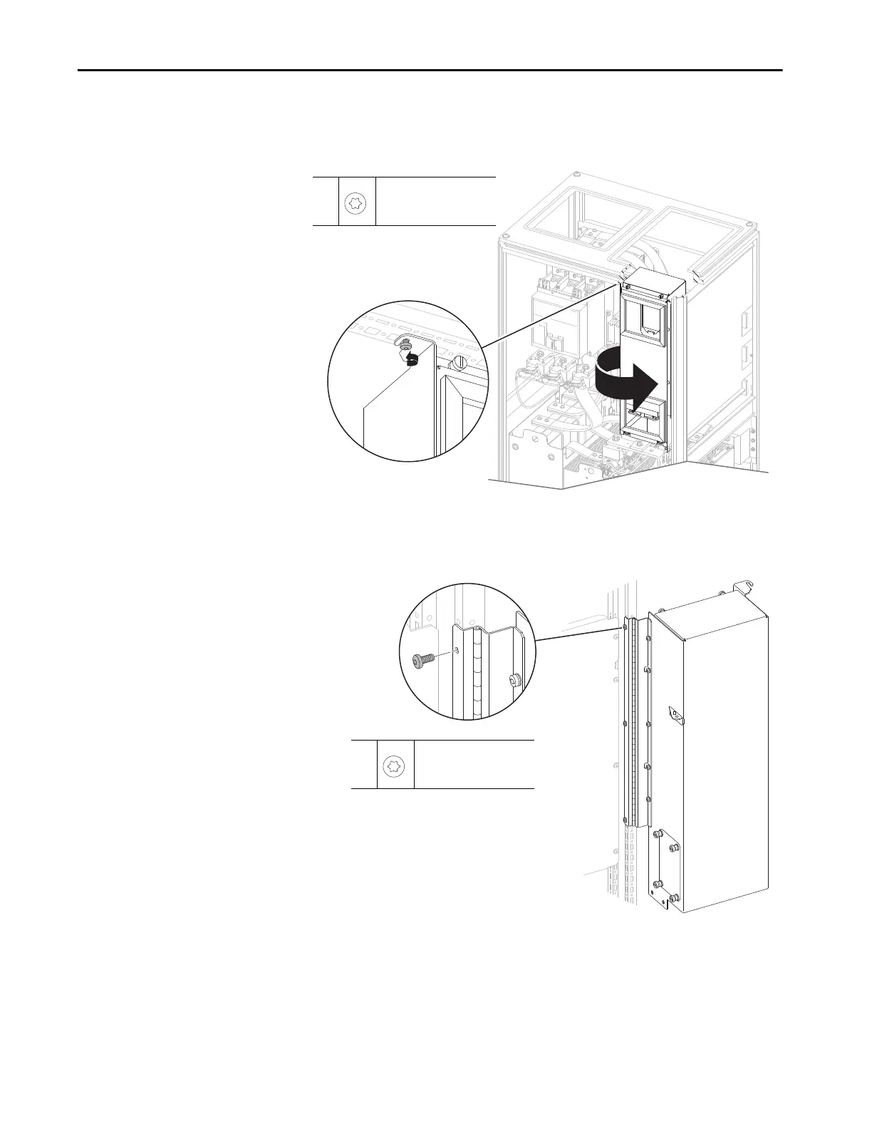
17. Loosen the M5.5 x 13 mm torx screw that secures the control pod
assembly to the chassis and rotate the control pod assembly out from the
enclosure.
18. While supporting the control pod assembly, remove the three M5.5 x
13 mm torx screws that secure the hinged mounting bracket to the inside
edge of the enclosure and remove the control pod assembly.
17
M5.5 x 13 mm
T25
4.8 N•m (42 lb•in)
18
M5.5 x 13 mm
T25
4.8 N
•m (42 lb•in)

Table of Contents

Other manuals for Rockwell Automation Allen-Bradley PowerFlex 750 Series

Questions and Answers:

Question and Answer IconNeed help?

Do you have a question about the Rockwell Automation Allen-Bradley PowerFlex 750 Series and is the answer not in the manual?

Rockwell Automation Allen-Bradley PowerFlex 750 Series Specifications

General IconGeneral
BrandRockwell Automation
ModelAllen-Bradley PowerFlex 750 Series
CategoryDC Drives
LanguageEnglish

Related product manuals