264 Rockwell Automation Publication 750-TG100B-EN-P - June 2019
Chapter 9 Power Bay Components
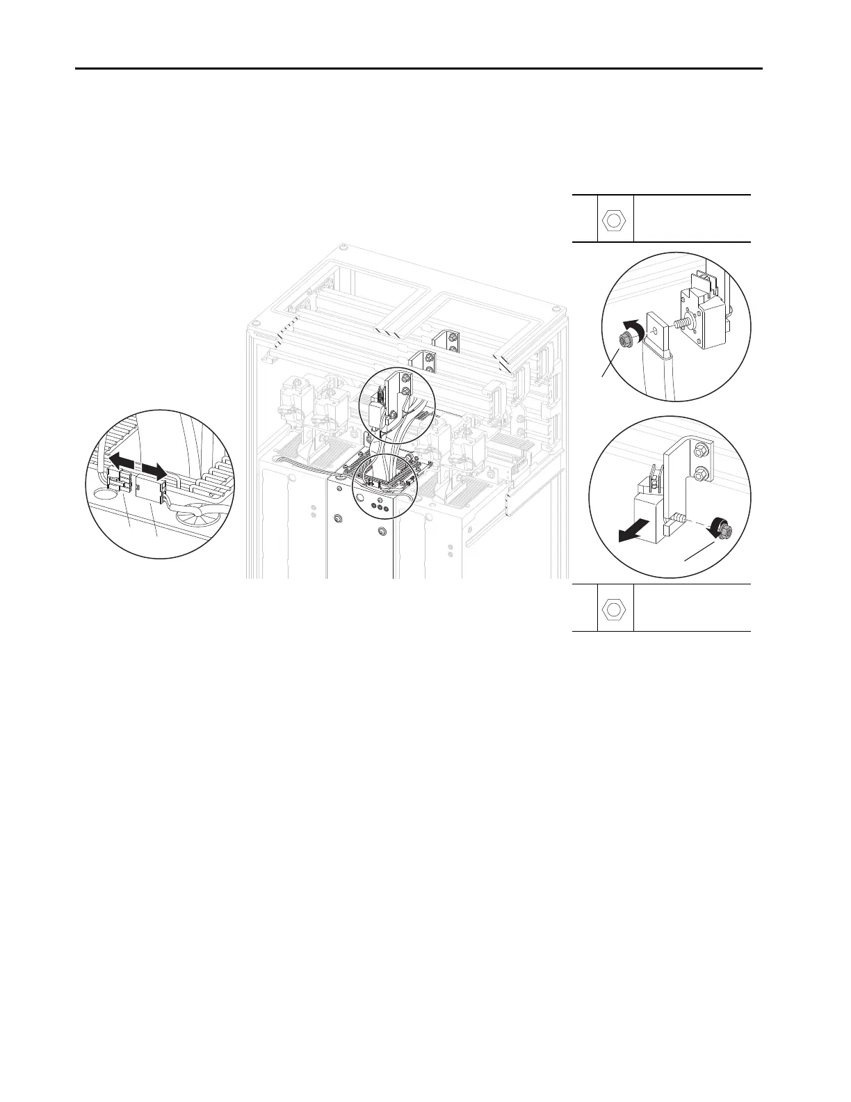
7. Remove the three M12 x 13 mm hex nuts that secure the flexible bus cables
to the AC input fuse terminals and remove the flexible bus cables.
8. Remove the three M12 x 13 mm hex nuts that secure the fuse to the AC
input bus bars and remove the fuses.
Install the AC Input Link Fuses
Install the AC input link fuses in the reverse order of removal.
LCL Filter Capacitor
Assembly Replacement
Replace the LCL filter module capacitor assembly with the appropriate kit
catalog number:
• SK-RM-LCLCP1-F8M (30 µF)
• SK-RM-LCLCP2-F8M (41 µF)
• SK-RM-LCLCP3-F8M (62 µF)
• SK-RM-LCLCP4-F8M (80 µF)
Remove the LCL Filter Capacitor Assembly
Follow these steps to remove and replace the LCL filter capacitor assembly.
7
M12 x 13 mm
19 mm
45 N•m (398 lb•in)
8
M12 x 13 mm
19 mm
45 N•m (398 lb•in)
Frame 9…12 Power Bay Shown
7
8

 Loading...


