94 Rockwell Automation Publication 750-TG100B-EN-P - June 2019
Chapter 5 Frame 6 Components
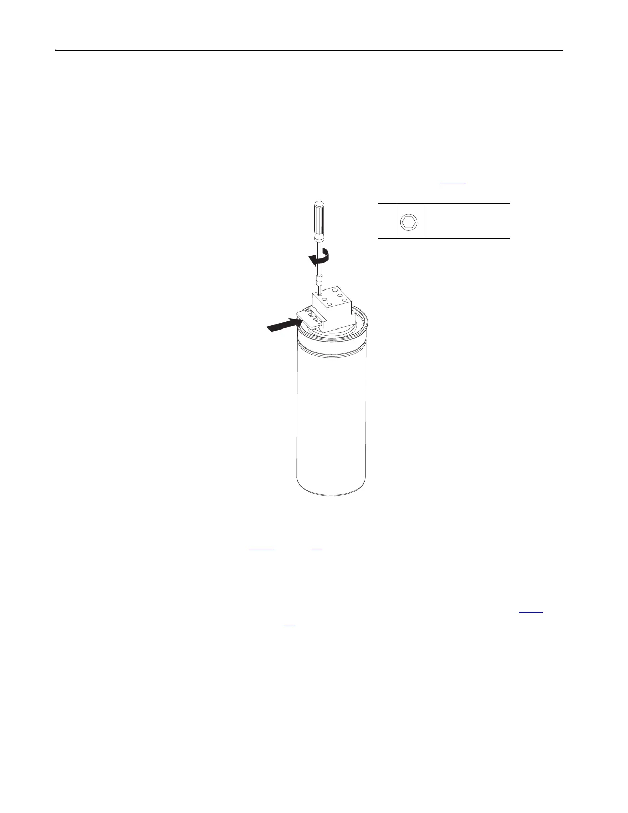
Install the LCL Filter Capacitor
Follow these steps to install a replacement LCL filter capacitor.
1. Insert all three legs of the resistor supplied with the kit into the terminal
block at the top of the capacitor and secure the resistor.
• When two capacitors are installed, a single resistor must be installed on
the left side of the left-most capacitor. See step 6
for wiring orientation.
2. If two capacitors are used, secure the interconnection wires to terminals R,
S and T on the capacitor terminal block at the top of both capacitors. See
step 6
on page 92 for wiring orientation.
3. Secure the wire harness from the power circuit board to terminals R, S and
T on the right side of the capacitor terminal block.
• When two capacitors are used, install the wire harness is connected to
the right side of the right-most capacitor terminal block. See step 6
on
page 92
for wiring orientation.
1
1
M5
3 mm
1.8 N•m (16.0 lb•in)

 Loading...


