EasyManuals Logo

Rockwell Automation Allen-Bradley PowerFlex 750 Series Service Manual

Rockwell Automation Allen-Bradley PowerFlex 750 Series
352 pages
To Next Page IconTo Next Page
To Previous Page IconTo Previous Page
Page #151 background imageLoading...
Page #151 background image
Rockwell Automation Publication 750-TG100B-EN-P - June 2019 151
Control Bay and Control Pod Components Chapter 7
Install the Fiber Transceiver Circuit Board
Install the fiber transceiver circuit board in the reverse order of removal.
When installing the fiber-optic cables:
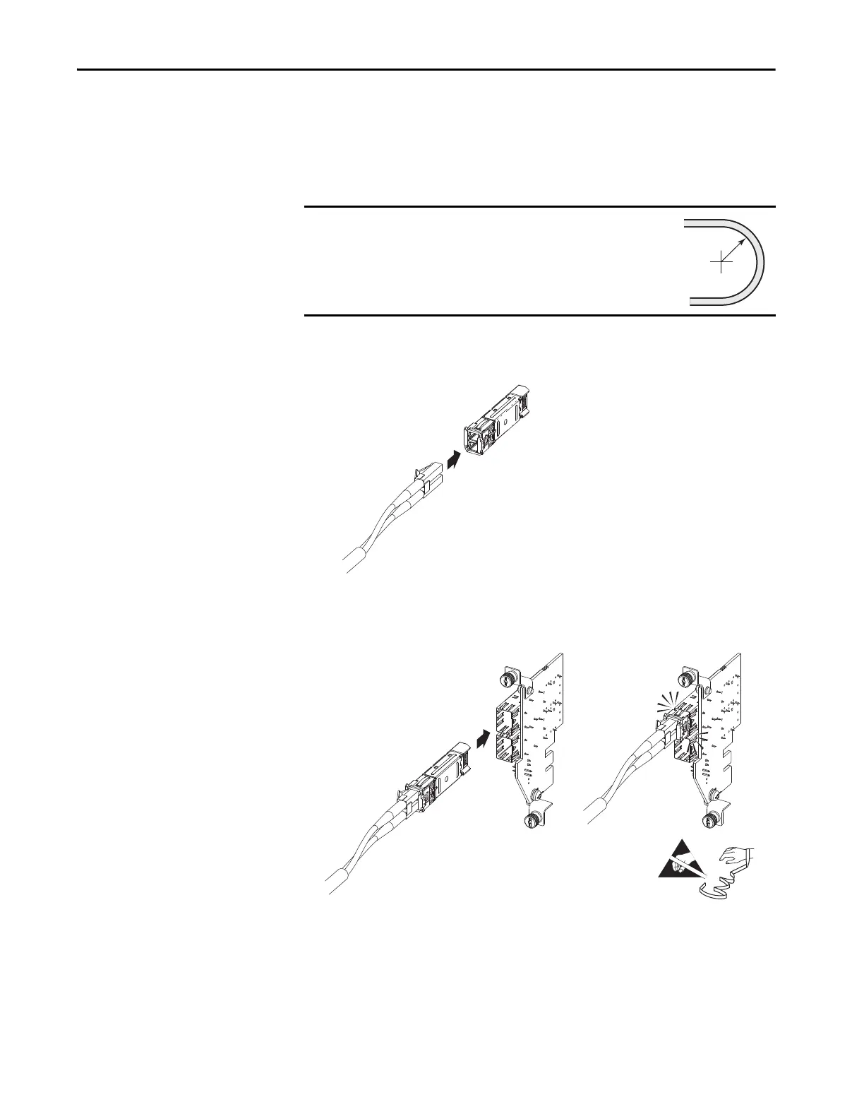
1. Without bending the cable to a radius less than 50 mm (2 in.), fully insert
the fiber-optic cable into the transceiver.
2. Insert the transceiver with fiber-optic cable into the port on the board,
until you hear an audible ‘click.’
IMPORTANT
Minimum inside bend radius for fiber-optic cable is 50 mm
(2 in.). Any bends with a shorter inside radius can
permanently damage the fiber-optic cable. Signal
attenuation increases as inside bend radius is decreased.
50 mm
(2 in.)
=

Table of Contents

Other manuals for Rockwell Automation Allen-Bradley PowerFlex 750 Series

Questions and Answers:

Question and Answer IconNeed help?

Do you have a question about the Rockwell Automation Allen-Bradley PowerFlex 750 Series and is the answer not in the manual?

Rockwell Automation Allen-Bradley PowerFlex 750 Series Specifications

General IconGeneral
BrandRockwell Automation
ModelAllen-Bradley PowerFlex 750 Series
CategoryDC Drives
LanguageEnglish

Related product manuals