EasyManuals Logo

Rockwell Automation Allen-Bradley PowerFlex 750 Series Service Manual

Rockwell Automation Allen-Bradley PowerFlex 750 Series
352 pages
To Next Page IconTo Next Page
To Previous Page IconTo Previous Page
Page #213 background imageLoading...
Page #213 background image
Rockwell Automation Publication 750-TG100B-EN-P - June 2019 213
Power Bay Components Chapter 9
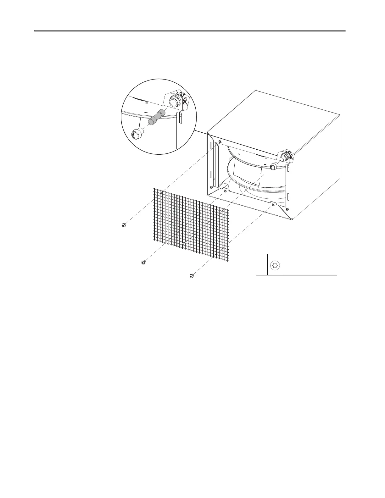
4. Remove the four M8 x 12 mm torx screws that secure the screen to the
front of the fan housing and remove the screen.
5. Unscrew the fuse holder and fuse and remove the fuse.
Install the IP54 Exhaust Fan Fuse
Install the IP54 exhaust fan fuse on a power bay in the reverse order of removal.
Tightening torque for the fuse holder is 3.4 N•m (30 lb•in).
4
M8 x 12 mm
T30
19.8 N•m (175 lb•in)

Table of Contents

Other manuals for Rockwell Automation Allen-Bradley PowerFlex 750 Series

Questions and Answers:

Question and Answer IconNeed help?

Do you have a question about the Rockwell Automation Allen-Bradley PowerFlex 750 Series and is the answer not in the manual?

Rockwell Automation Allen-Bradley PowerFlex 750 Series Specifications

General IconGeneral
BrandRockwell Automation
ModelAllen-Bradley PowerFlex 750 Series
CategoryDC Drives
LanguageEnglish

Related product manuals