EasyManuals Logo

Rockwell Automation Allen-Bradley PowerFlex 750 Series Service Manual

Rockwell Automation Allen-Bradley PowerFlex 750 Series
352 pages
To Next Page IconTo Next Page
To Previous Page IconTo Previous Page
Page #92 background imageLoading...
Page #92 background image
92 Rockwell Automation Publication 750-TG100B-EN-P - June 2019
Chapter 5 Frame 6 Components
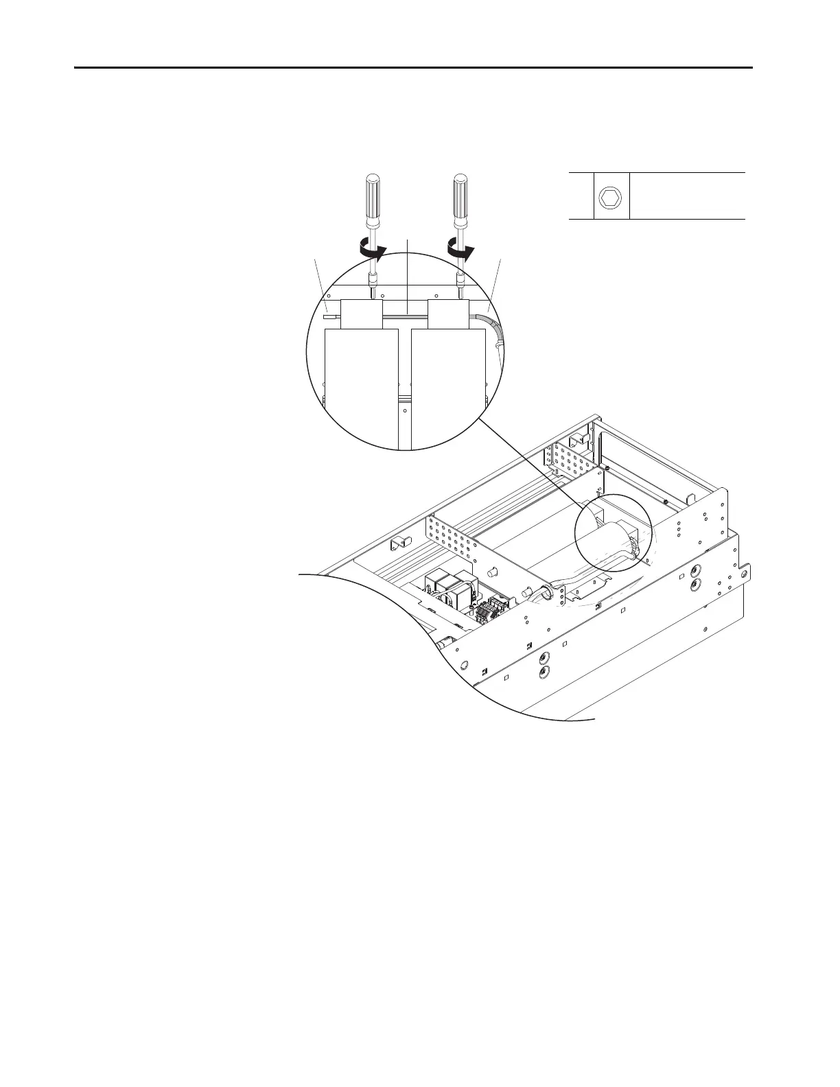
6. Loosen the M5 hexagonal screws that secure the capacitor wires to
terminals R, S and T on the capacitor terminal block at the top of the
capacitor, and remove the wires. Retain all wires for reuse.
Resistor
Interconnection
Wires
From Power
Circuit Board
6
M5
3 mm
1.8 N
•m (16.0 lb•in)

Table of Contents

Other manuals for Rockwell Automation Allen-Bradley PowerFlex 750 Series

Questions and Answers:

Question and Answer IconNeed help?

Do you have a question about the Rockwell Automation Allen-Bradley PowerFlex 750 Series and is the answer not in the manual?

Rockwell Automation Allen-Bradley PowerFlex 750 Series Specifications

General IconGeneral
BrandRockwell Automation
ModelAllen-Bradley PowerFlex 750 Series
CategoryDC Drives
LanguageEnglish

Related product manuals