EasyManuals Logo

Rockwell Automation Allen-Bradley PowerFlex 750 Series Service Manual

Rockwell Automation Allen-Bradley PowerFlex 750 Series
352 pages
To Next Page IconTo Next Page
To Previous Page IconTo Previous Page
Page #170 background imageLoading...
Page #170 background image
170 Rockwell Automation Publication 750-TG100B-EN-P - June 2019
Chapter 7 Control Bay and Control Pod Components
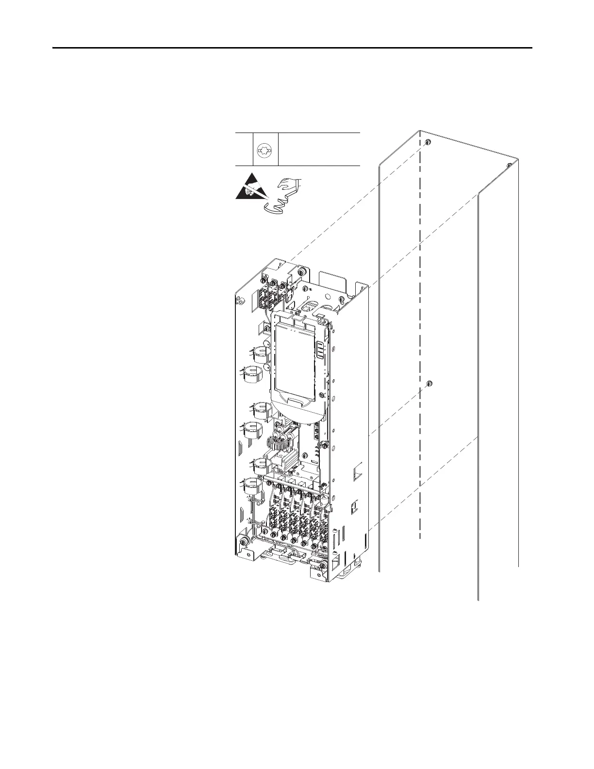
16. Loosen the four M4 x 8 mm torx screws that secure the pod chassis to the
back panel.
17. Slide the pod up, so that the keyholes on the pod clear the mounting
screws, and remove the control pod.
16
M4 x 8 mm
T20 or F - 5 mm (0.19 in.)
2.6 N•m (23 lb•in)
=

Table of Contents

Other manuals for Rockwell Automation Allen-Bradley PowerFlex 750 Series

Questions and Answers:

Question and Answer IconNeed help?

Do you have a question about the Rockwell Automation Allen-Bradley PowerFlex 750 Series and is the answer not in the manual?

Rockwell Automation Allen-Bradley PowerFlex 750 Series Specifications

General IconGeneral
BrandRockwell Automation
ModelAllen-Bradley PowerFlex 750 Series
CategoryDC Drives
LanguageEnglish

Related product manuals