230 Rockwell Automation Publication 750-TG100B-EN-P - June 2019
Chapter 9 Power Bay Components
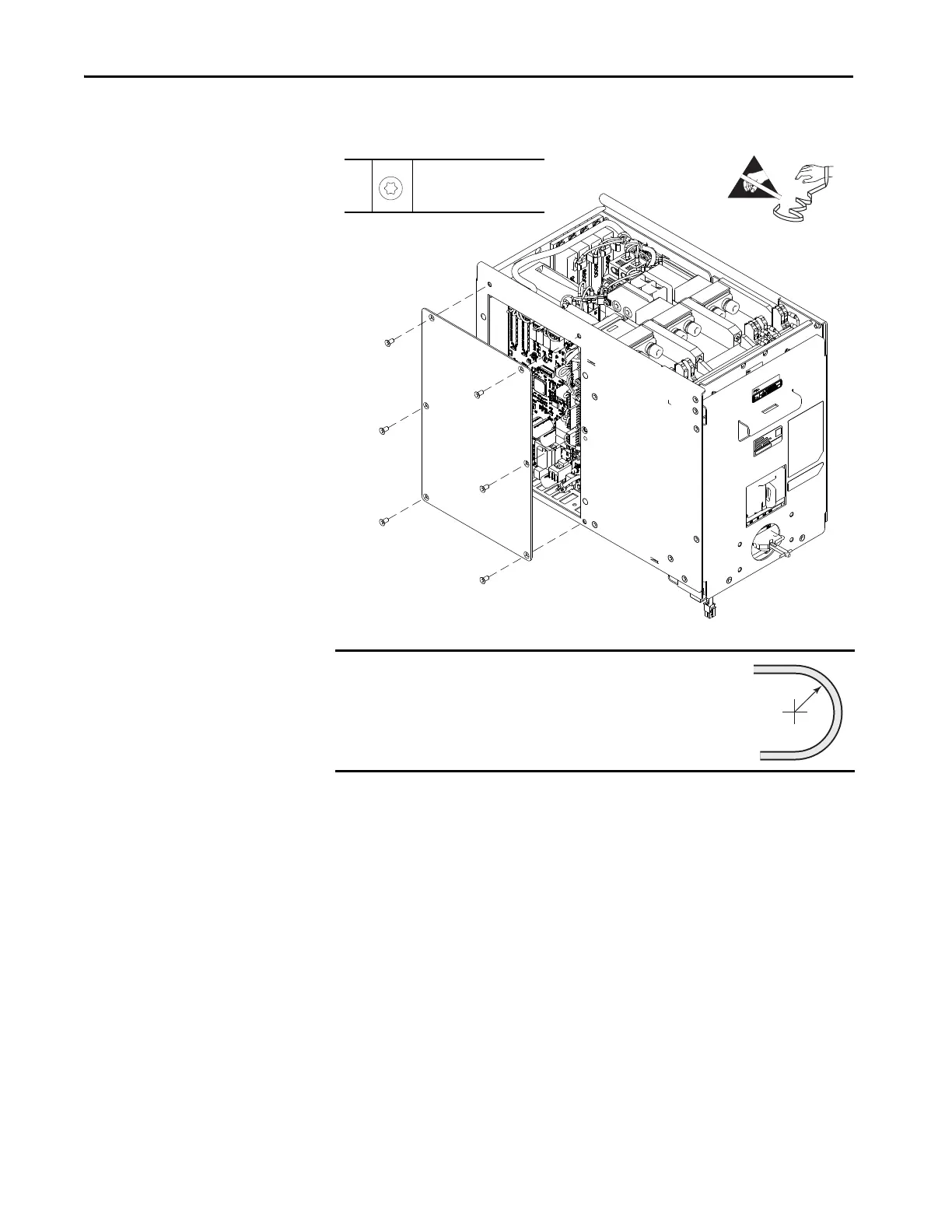
5. Remove the six M5 x 10 mm torx screws that secure the circuit board cover
to the DC precharge chassis.
6. Without bending the cable to a radius less than 50 mm (2 in.), remove the
fiber-optic cable from the transceiver in the DCP port on the DC
precharge circuit board.
7. Remove the transceiver from the DCP port on the DC precharge circuit
board. Retain the transceiver for reuse.
8. Disconnect these cable connectors from the DC precharge circuit board:
•P1 from J1
•P2 from J2
•P3 from J3
•P9 from J9
• P10 from J10
IMPORTANT
Minimum inside bend radius for fiber-optic cable is 50 mm
(2 in.). Any bends with a shorter inside radius can
permanently damage the fiber-optic cable. Signal
attenuation increases as inside bend radius is decreased.
5
M5 x 10 mm
T25
2.8 N
•m (25 lb•in)

 Loading...


