Rockwell Automation Publication 750-TG100B-EN-P - June 2019 239
Power Bay Components Chapter 9
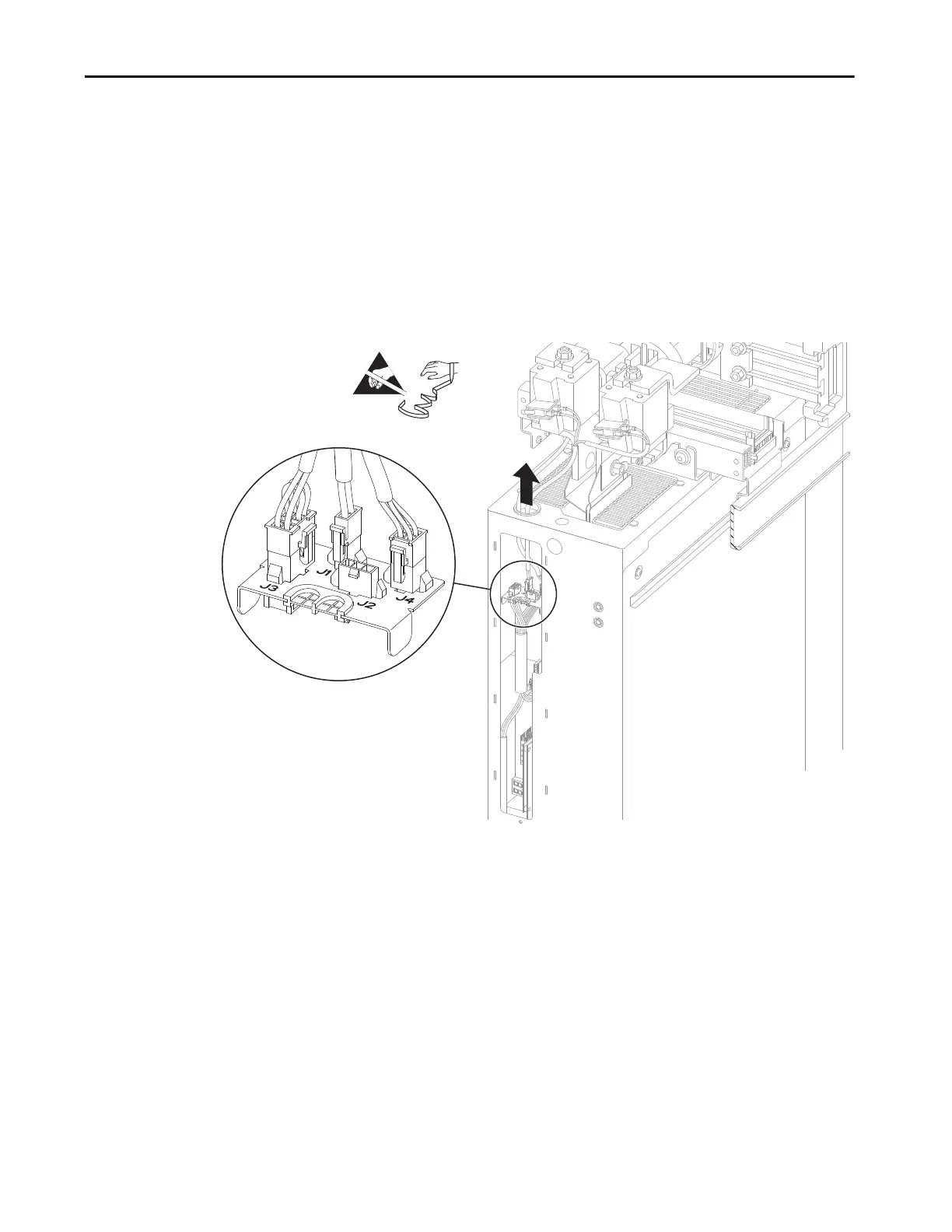
9. If present, disconnect the cable connector P1 from connector J1 on the I/
O panel in the power module remove the cable from the power module
chassis.
10. If present, disconnect the cable connector P2 from connector J2 on the I/
O panel in the power module remove the cable from the power module
chassis.
11. Disconnect the cable connector P3 from connector J3 on the I/O panel in
the power module remove the cable from the power module chassis.
12. Disconnect the cable connector P4 from connector J4 on the I/O panel in
the power module remove the cable from the power module chassis.

 Loading...


