EasyManuals Logo

Rockwell Automation Allen-Bradley PowerFlex 750 Series Service Manual

Rockwell Automation Allen-Bradley PowerFlex 750 Series
352 pages
To Next Page IconTo Next Page
To Previous Page IconTo Previous Page
Page #259 background imageLoading...
Page #259 background image
Rockwell Automation Publication 750-TG100B-EN-P - June 2019 259
Power Bay Components Chapter 9
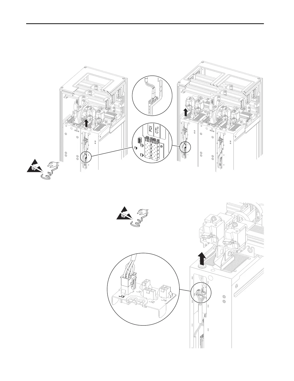
7. Without bending the cable to a radius less than 50 mm (2 in.), disconnect
the fiber-optic cable from the transceiver in the PDI and CTL port on the
power layer interface circuit board and carefully remove one or more cables
from the power module chassis.
8. Disconnect the 24V cable connector P3 from connector J3 on the I/O
panel in one or more power modules and remove the cable from the
chassis.
LCL filter with one line side converter. LCL filter with two line side converters.
=
P3
=

Table of Contents

Other manuals for Rockwell Automation Allen-Bradley PowerFlex 750 Series

Questions and Answers:

Question and Answer IconNeed help?

Do you have a question about the Rockwell Automation Allen-Bradley PowerFlex 750 Series and is the answer not in the manual?

Rockwell Automation Allen-Bradley PowerFlex 750 Series Specifications

General IconGeneral
BrandRockwell Automation
ModelAllen-Bradley PowerFlex 750 Series
CategoryDC Drives
LanguageEnglish

Related product manuals