EasyManuals Logo

Rockwell Automation Allen-Bradley PowerFlex 750 Series Service Manual

Rockwell Automation Allen-Bradley PowerFlex 750 Series
352 pages
To Next Page IconTo Next Page
To Previous Page IconTo Previous Page
Page #266 background imageLoading...
Page #266 background image
266 Rockwell Automation Publication 750-TG100B-EN-P - June 2019
Chapter 9 Power Bay Components
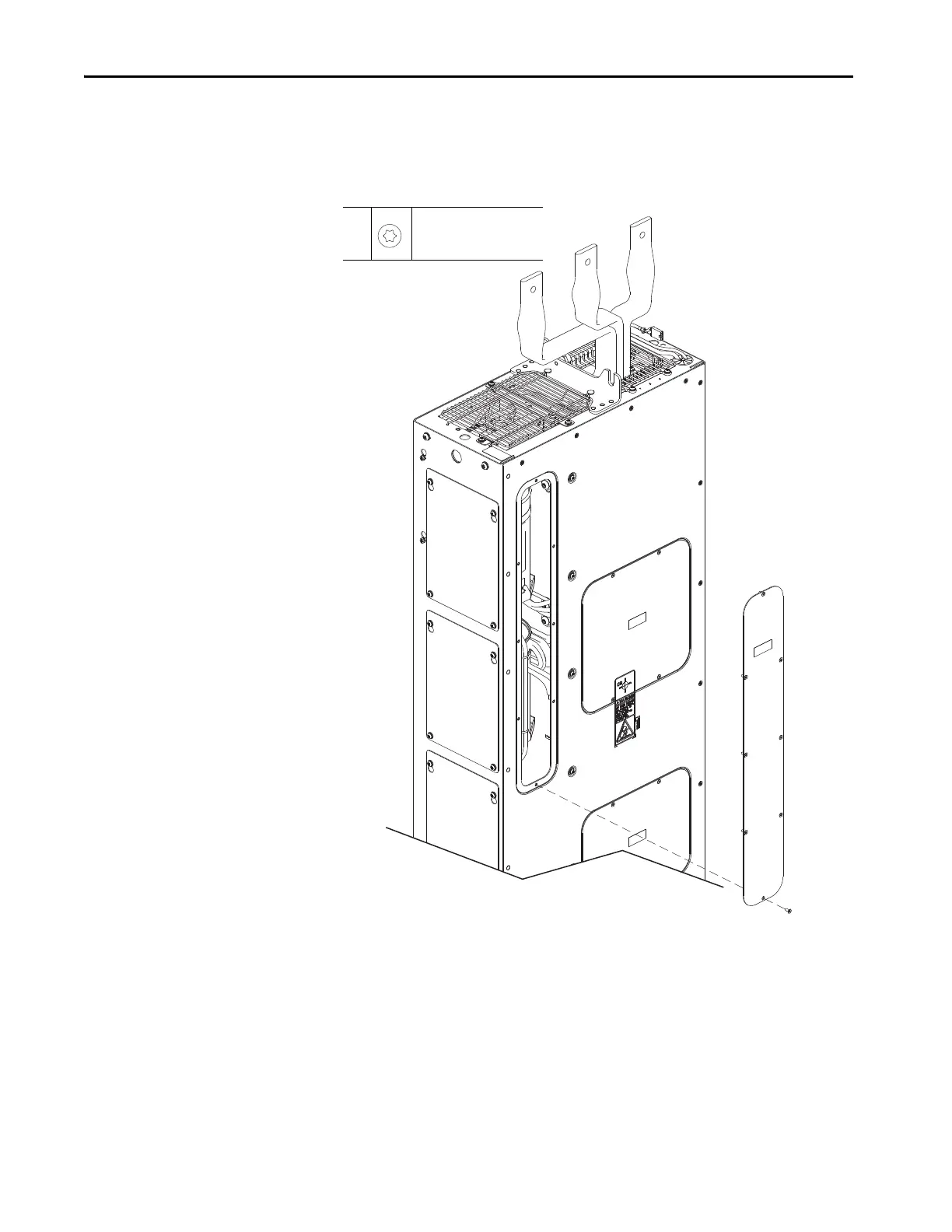
5. Remove the wire access cover to more easily feed the wiring through the
back of the chassis when a capacitor assembly is removed. Remove the
eight M4 x 10 mm torx screws that secure the capacitor wire access cover to
the chassis and remove the cover.
5
M4 x 10 mm
T25
3 N•m (26 lb•in)

Table of Contents

Other manuals for Rockwell Automation Allen-Bradley PowerFlex 750 Series

Questions and Answers:

Question and Answer IconNeed help?

Do you have a question about the Rockwell Automation Allen-Bradley PowerFlex 750 Series and is the answer not in the manual?

Rockwell Automation Allen-Bradley PowerFlex 750 Series Specifications

General IconGeneral
BrandRockwell Automation
ModelAllen-Bradley PowerFlex 750 Series
CategoryDC Drives
LanguageEnglish

Related product manuals