278 Rockwell Automation Publication 750-TG100B-EN-P - June 2019
Chapter 9 Power Bay Components
3. Open the corresponding power bay enclosure door.
4. Remove the right-most power module from the enclosure. See Power
Module Replacement from the Enclosure on page 236
.
5. Without bending the cable to a radius less than 50 mm (2 in.), remove the
fiber-optic cable from the transceiver in the TAM port on the torque
accuracy module.
6. Remove the transceiver from the TAM port on the board. Retain the
transceiver for reuse.
7. Disconnect connector P1 from J1 on the torque accuracy module.
8. Disconnect connector P2 from J2 on the torque accuracy module.
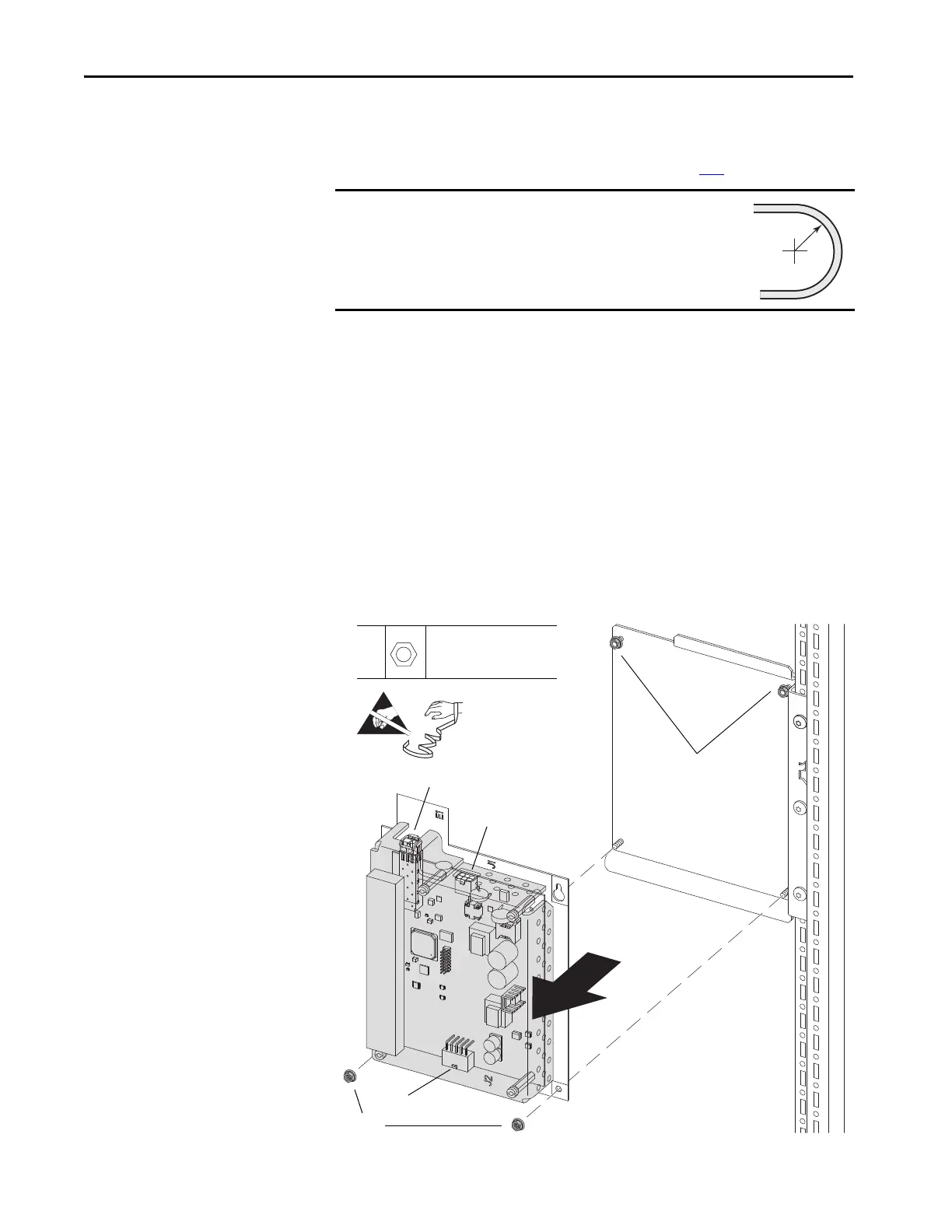
9. Loosen the two upper M4 hex nuts and washers that secure the torque
accuracy module panel to the mounting bracket.
10. Remove the lower two M4 hex nuts and washers that secure the torque
accuracy module panel to the mounting bracket and remove the module
and panel.
IMPORTANT
Minimum inside bend radius for fiber-optic cable is 50 mm
(2 in.). Any bends with a shorter inside radius can
permanently damage the fiber-optic cable. Signal
attenuation increases as inside bend radius is decreased.
9,
10
M4
7 mm
2.6 N•m (23 lb•in)

 Loading...


