EasyManuals Logo

Rockwell Automation Allen-Bradley PowerFlex 750 Series Service Manual

Rockwell Automation Allen-Bradley PowerFlex 750 Series
352 pages
To Next Page IconTo Next Page
To Previous Page IconTo Previous Page
Page #281 background imageLoading...
Page #281 background image
Rockwell Automation Publication 750-TG100B-EN-P - June 2019 281
Power Bay Components Chapter 9
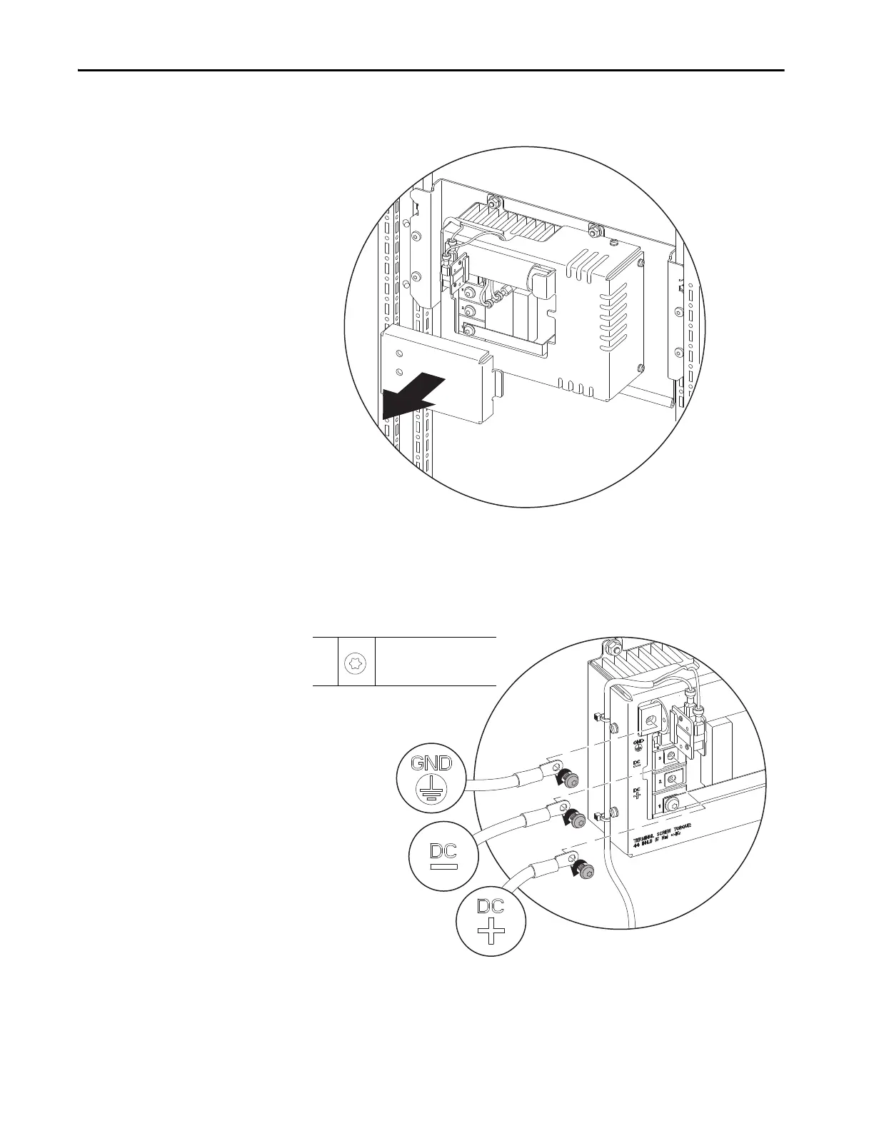
8. Remove the clear-plastic connections cover from the front of the DC bus
conditioner.
9. Remove the two M6 x 12 mm torx screws that secure the +DC and -DC
cables to the +DC and -DC terminals on the DC bus conditioner,
respectively, and remove the cables.
10. Remove the M6 x 12 mm torx screw that secures the ground cable to the
GND (PE) terminal on the DC bus conditioner and remove the cable.
9,
10
M6 x 12 mm
T30
5 N•m (44 lb•in)

Table of Contents

Other manuals for Rockwell Automation Allen-Bradley PowerFlex 750 Series

Questions and Answers:

Question and Answer IconNeed help?

Do you have a question about the Rockwell Automation Allen-Bradley PowerFlex 750 Series and is the answer not in the manual?

Rockwell Automation Allen-Bradley PowerFlex 750 Series Specifications

General IconGeneral
BrandRockwell Automation
ModelAllen-Bradley PowerFlex 750 Series
CategoryDC Drives
LanguageEnglish

Related product manuals