304 Rockwell Automation Publication 750-TG100B-EN-P - June 2019
Appendix A System Schematics
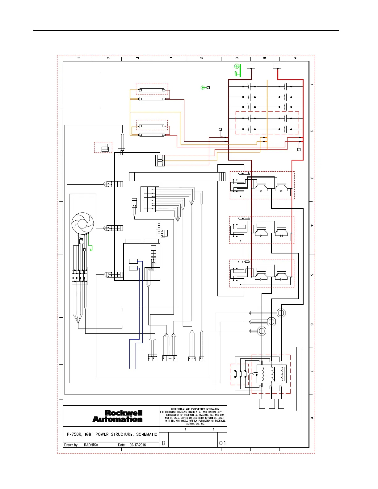
Figure 27 - PowerFlex 755TM Power Module (Frames 8…15)
(PCBA1)
240VAC_N
240VAC_H
1234
1234
J4
5
5
12
J11
12
CUST_COM
CUST_+24V
(PCBA2)
PLI BOARD
64 PINS
J18
PDI
FIBER LINK to Mx-POD1
FIBER LINK to DCP / LCL
8
9
10
11
1
2
3
4
12
13
14
5
6
714
13
11
12
7
6
5
4
10
9
8
3
2
1
J10
J13
4
2
3
1
BLOWER_FDBK
BLOWER_COM
BLOWER_CONTROL
INTAKE_TEMP_A
INTAKE_TEMP_B
+24 OUT
/AC FUSE GOOD
AC FUSE COM
COM OUT
DC FUSE COM
/DC FUSE GOOD
CONV_B_TEST
CONV_A_TEST
CONV_VARY_B
CONV_VARY_A
BUS_COND_COM
/BUS_COND_PRESENT
/BUS_COND_GOOD
P13
1
3
2
4
P4
P10
P11
PF750R, IGBT PS, SCHEMATIC
PE-B1 IN
PE-B1 OUT
P12
NTC
GATE BOARD
(PCBA3)
LEM
W
V
LEM
BLOWER
F1
240VAC_N
10V CNTRL REF
BLOWER_FDBK
240VAC_H
BLOWER_COM
BLOWER_CONTROL
INTAKE_TEMP_A
INTAKE_TEMP_B
FAN1
NTC
P13
J13
-NEG
-NEG
MID
MID
+POS
+POS
C1
+
-
++ + +
IGBT1 IGBT2 IGBT3
R4
R2
R3
R1
CS1
CS2
CS3
L1
R5
R6
R7
POS BUS BAR
NEG BUS BAR
MID BUS BAR
U/T1
V/T2
W/T3
+DC
-DC
OPTIONAL
ONLY FOR FR-8C
12
34
12
5
6
7
8
1
2
3
4
123
J1
J2
J3
J4
ONLY FOR FR-8C
ONLY FOR FR-8C
OPTIONAL
(ONLY FOR 20-750-MI3-xxxxxxx)
U-Phase
IGBT
V-Phase
IGBT
W-Phase
IGBT
Size
Sheet Of
Ver
10001416614
U
LEM
64 PINS
J19
/BUS_COND_PRESENT
BUS_COND_COM
/BUS_COND_GOOD
NTC
NTC
12
3
4
J7
21
43
12 3
32
J12
1
5
6
7
8
1
3
2
4
5
6
7
8
1
2
3
4
P1
40 PINS
J1
40 PINS
P3
J3
1
2
1
2
5
4
3
1
23
4
1
3
2
4
1
23
4
1
2
1
2
1
2
2
1
1
2
3
4
1
3
2
4
1
2
3
4
4
3
2
1
2
1
2
1
1
2
3
1
2
3
1
2
1.
3.
2.
4.
1
23
4
12
3
4
J8
21
43
1
3
2
4
12
3
4
J9
21
43
1
3
2
4
40 PIN RIBBON CABLE
/DC FUSE GOOD
DC FUSE COM
CUST_+24V
CUST_COM
4
+24V
-24V
M
VRFY
+24V
-24V
M
VRFY
+POS
-NEG
MID
1
2
4
3
5
C3 C5 C7 C9
-
- - -
C2
+
-
++ + +
C4 C6 C8 C10
-
- - -
CATALOG NUMBER: 20-750-MIx-xxxxxxxx
CHASSIS
Thermal Switch(N/C)
TO
J12-PCBA1
CHASSIS
(STABS)
R1-1
R3-1
R2-1
R4-1
R1-2
R3-2
R2-2
R4-2
12
3
P12
(ONLY FOR 20-750-MI1-xxxxxxx)
+24V
-24V
M
VRFY
+24 OUT
/AC FUSE GOOD
AC FUSE COM
COM OUT
CONV_B_TEST
CONV_A_TEST
CONV_VARY_B
CONV_VARY_A
240VAC_N
240VAC_H
FFE Converter only, otherwise should be
connected to J6(PE-B1 OUT)
TP1
+DC
TP2
-DC
TP1= +DC
TP2= -DC
Label for Test Points on Front
TP3
TP3= Chassis
BLOWER_FDBK
BLOWER_COM
BLOWER_CONTROL
INTAKE_TEMP_A
INTAKE_TEMP_B
P5/P6 must be connected to J5(PE-B1 IN) For
CTL
1234
J5
1234
J6
12
3
4
P5/P6
On Panel, IGBT PS
On Panel, IGBT PS
On Panel, IGBT PS
On Panel, IGBT PS
On Panel, IGBT PS
On Panel, IGBT PS
CS3_VERY
CS3_+24V
CS3_M
CS3_-24V
1.
2.
3.
4.
Thermal switch_2
Thermal switch_1
1.
2.
CS2_VERY
CS2_+24v
CS2_M
CS2_-24V
1.
2.
3.
4.
CS1_VERY
CS1_+24V
CS1_M
CS1_-24V
1.
2.
3.
4.
Fiberlink
Fiberlink
U/T1 Busbar
V/T2 Busbar
W/T3 Busbar

 Loading...


