PCM Synth Tone (PCMS) – STEP LFO tab
61
Parameter Value Explanation
Oset -100, -50, 0, +50, +100
Raises or lowers the LFO waveform relative to the central value (pitch or cuto frequency). Positive “+”
settings will move the waveform so that modulation will occur from the central value upward. Negative
“-” settings will move the waveform so that modulation will occur from the central value downward.
Delay Time 0–127
Delay Time (LFO Delay Time) species the time elapsed before the LFO eect is applied (the eect
continues) after the key is pressed (or released).
* After referring to “How to Apply the LFO” (p. 62), change the setting until the desired eect is
achieved.
MEMO
When using violin, wind, or certain other instrument sounds in a performance, rather than
having vibrato added immediately after the sounds are played, it can be eective to add the
vibrato after the note is drawn out somewhat. If you set the Delay Time in conjunction with the
Pitch Depth parameter and Rate parameter, the vibrato will be applied automatically following
a certain interval after the key is pressed. This eect is called “Delay Vibrato.”
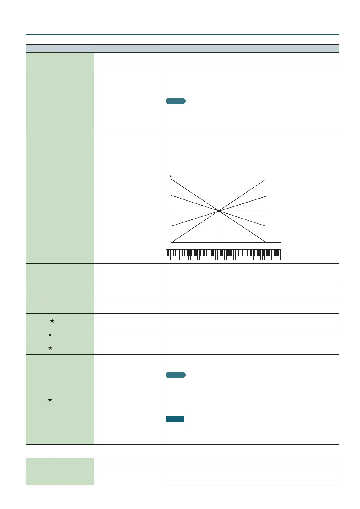
Delay Time KF -100–+100
Adjusts the value for the Delay Time parameter depending on the key position, relative to the
C4 key (center C). To decrease the time that elapses before the LFO eect is applied (the eect is
continuous) with each higher key that is pressed in the upper registers, select a positive value; to
increase the elapsed time, select a negative value. Larger settings will produce greater change.
If you do not want the elapsed time before the LFO eect is applied (the eect is continuous) to
change according to the key pressed, set this to “0.”
C4C3C2C1 C5 C6 C7
0
+50
+100
-50
-100
Key
Time
Fade Mode ON<, ON>, OFF<, OFF>
Species how the LFO will be applied.
* After referring to “How to Apply the LFO” (p. 62), change the setting until the desired eect is
achieved.
Fade Time 0–127
Species the time over which the LFO amplitude will reach the maximum (minimum).
* After referring to “How to Apply the LFO” (p. 62), change the setting until the desired eect is
achieved.
Key Trigger OFF, ON
Species whether the LFO cycle will be synchronized to begin when the key is pressed (ON) or not
(OFF).
Pitch Depth
-63–+63
Species how deeply the LFO will aect pitch.
* You can control this parameter using the Matrix Control.
TVF Depth
-63–+63
Species how deeply the LFO will aect the cuto frequency.
* You can control this parameter using the Matrix Control.
TVA Depth
-63–+63
Species how deeply the LFO will aect the volume.
* You can control this parameter using the Matrix Control.
Pan Depth
-63–+63
Species how deeply the LFO will aect the pan.
* You can control this parameter using the Matrix Control.
MEMO
Positive “+” and negative “-” settings for the Depth parameter result in diering kinds of
change in pitch and volume. For example, if you set the Depth parameter to a positive “+”
value for one partial, and set another partial to the same numerical value, but make it negative
“-”, the modulation phase for the two partials will be the reverse of each other. This allows you
to shift back and forth between two dierent partials, or combine it with the Pan setting to
cyclically change the location of the sound image.
NOTE
In the Pan Depth parameter settings, if the Structure Type parameter is set to any value from
“2” through “10,” the output of partial 1 and 2 will be combined into partial 2, and the output
of partial 3 and 4 will be combined into partial 4. For this reason, partial 1 will follow the
settings of partial 2, and partial 3 will follow the settings of partial 4 (p. 52).
STEP LFO tab
Step Type TYP1, TYP2
When generating an LFO waveform from the data specied in LFO Step1–16, specify whether the
level will change abruptly at each step (TYP1) or will be connected linearly (TYP2).
LFO Step1-16 -36–+36
Species the data for the Step LFO.
If the LFO Pitch Depth is +63, each +1 unit of the step data corresponds to a pitch of +50 cents.

 Loading...