23
Chapter 1 Introduction
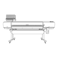
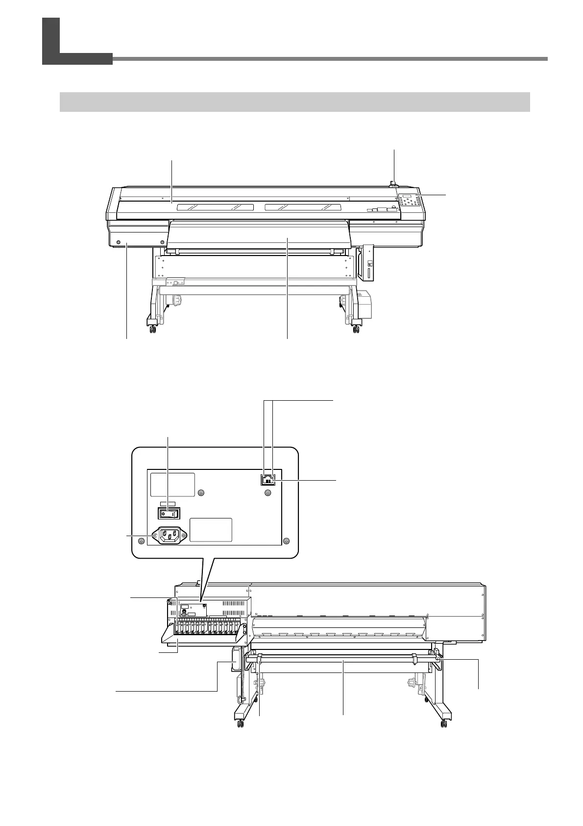
1-2 Part Names and Functions
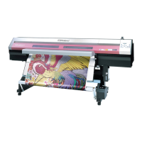
Printer Unit and Dryer
Dryer
This heats the media to hasten
ink-drying.
Maintenance cover
You remove this when you per-
form cleaning of the print heads.
Operation panel
You use this to perform
various operations.
☞
P. 25, "Operation Panel"
Loading lever
You operate this when you
load media.
Front cover
Be sure to close this when
you perform output.
Brake
This helps to ensure
stable media feed.
ShaftStopper
Link indicator
These LEDs indicate the network-connection sta-
tus. The green link LED lights up when connected
reliably. While receiving data, the yellow status
LED flashes.
Ethernet connector
This is used to connect the
printer to a network.
Main power switch
Ink-cartridge tray
Cartridge slots
There are where ink cartridges
are installed.
Drain bottle
This collects drained ink and
other such fluids.
Power-cord con-
nector
This supplies power
to the printer.

 Loading...