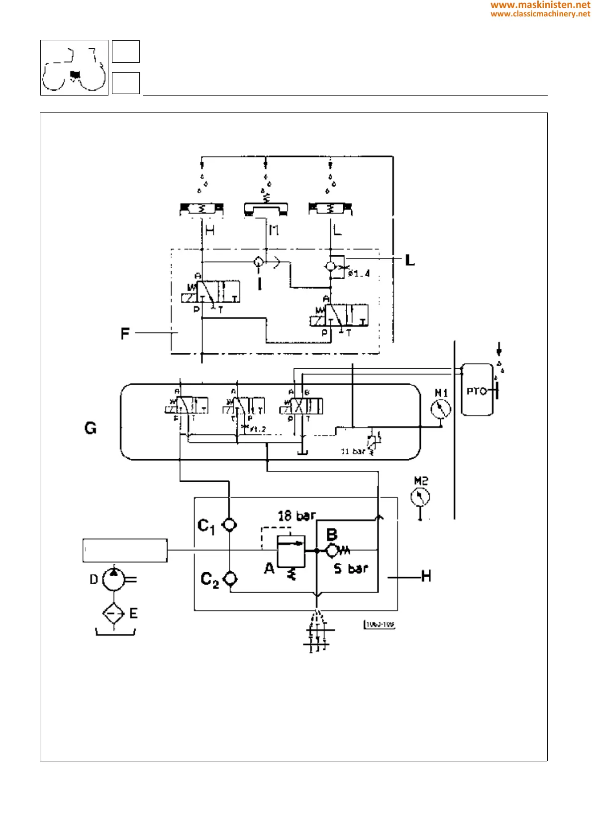
Fig. 12 - Hydraulic diagram illustrating operation.
clutch transmission
agroshift
A - sequence valve (operating pressure 18 bar)
B - transmission lubricant pressure regulator
(setting 4 bar)
C - check valve 30 l/min
D - oil pump (flow rate 10 ÷ 30 l/ min)
E - suction filter (25 m)
F - solenoid valves assembly
G - power unit for electrohydraulic
control functions
H - oil pressure control valves assembly
I - bistable valve
L - modulating valve
M1 - pressure gauge scale 0 ÷ 40 bar
M2 - pressure gauge scale 10 bar
T - return
Hydrostatic steering
4WD
D. Lock
27
2
128
www.maskinisten.net
www.classicmachinery.net