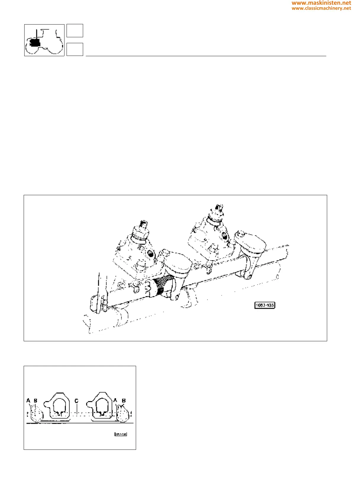
Fig. 1 - Injection pump control assembly.
Fig. 2 - Mounting positions of the injection pump
control bar guide supports.
Injection pump control system
The injection pumps are simultaneously controlled by a blank
sheet steel bar which besides ensuring the required stiffness has
particular lightweight properties to prevent excessive friction and
inertia under operating conditions.
This bar controls the injection pumps operating through specially
arranged slots and is connected to the engine governor by a
ratchet.
The injection pump control bar is guided by a couple of block-
mounted supports provided with slide rings.
Fuel injection pumps
The single-cylinder fuel injection pumps are equipped with a constant-pressure backflow valve (short G.D.V. valve).
The plunger load is evenly distributed over the whole camshaft, since an equal-distance distribution is provided.
The G.D.V. valve keeps pressure inside the injection pipes to a high level during the intermediate pump delivery phases.
This ensures engine smooth running even at low operating speed, higher engine performance as well as more
favourable torque curves, besides suppressing any nozzle dribbles resulting in unburnt gas, poor injection nozzle
efficiency and engine detonation.
Readings must be taken with the electrical systems powered (ignition keyswitch on), whereas resistance must be
measured with the battery disconnected.
engine
fuel system
16
1
74
www.maskinisten.net
www.classicmachinery.net