Fig. 11 - Control lever positions for lifting control
lever adjustment (yellow).
Fig. 12 - Control lever positions for working depth
control lever adjustment (green).
Fig. 13 - Adjusting lifting lever regulating tie rod
(yellow).
Fig. 14 - Adjusting green lever setscrew.
Adjusting power-lift system
NOTE: Before beginning with power-lift adjustment procedure
apply a 200 kg weight to the 3-point hitch.
Adjusting lifting control lever (yellow)
Figs. 11 - 13 - 15 - 16
With engine running, move the yellow lever all the way back and
the green lever all the way forward and ensure:
— lever A is contacting its own stop B; otherwise adjustment is
obtained through fork C;
— the lifting piston upper edge is fully aligned with the cylinder
edge; otherwise operate tie rod E.
Adjusting working depth control lever (green)
Figs. 12 - 14 - 15 - 16
With engine running, move the yellow lever forward against its
stop, just before "FLOAT" position, and the green lever onto
number 4 in its sector, then operate as follows:
— ensure the power-lift piston protrudes 5
− 1
0
mm from cylinder,
otherwise screw F should be adjusted;
— bring the green lever fully forward and then move it backward
gradually, making sure that the lifting action begins when
number 4 position is approached; otherwise operate fork G.
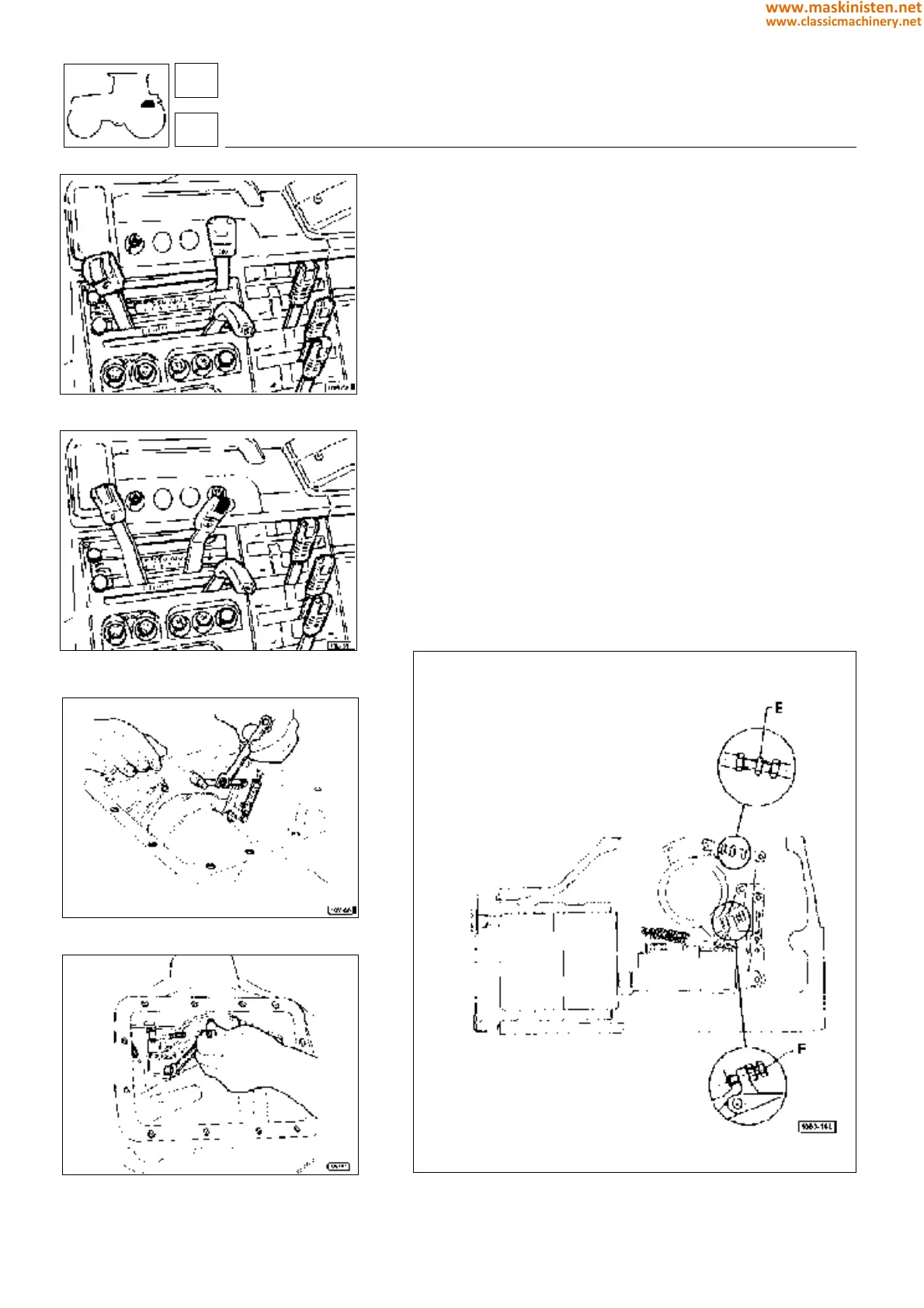
Fig 15 - Rod and screw for adjustment of yellow and green levers.
E - Yellow lever stop rod
F - Green lever adjustment screw
59
5
vehicle
rear hydraulic power-lift
272
www.maskinisten.net
www.classicmachinery.net