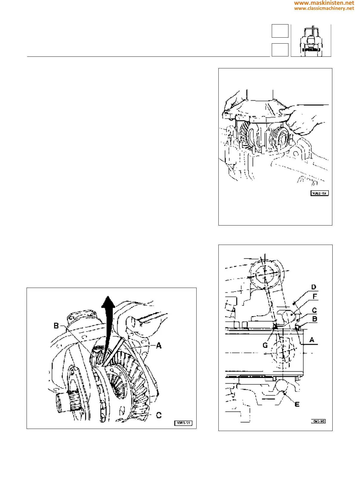
Internal adjustment of mechanical type differential
lock (fig 22)
(For adjustment of the external control linkage, see the "controls"
chapter).
1 - Assemble the components, locating all shims A on the side of
the circlip B; the overall thickness of the shims must be such that
clearance at the spacer C is between 0 and 0.05 mm.
2 - Move the sleeve D and check that the flat surface E engages
the ball F at the position indicated in fig 22.
3 - If this is not the case, remove the circlip B, and transfer a pack
of shims 0.20 mm thick to the other side of the spacer C, in position
G.
Complete the assembly and check that the condition of point 2 is
satisfied; if not, repeat the procedureadjusting the mechanical-
type differential lock internally
Installing the differential assembly into the drive
axle
Swivel the assembly so that the differential lock sleeve is brought
in the same side as the internal control lever. The sleeve should
be moved outwards to enable the lever pad to be housed inside
the groove. After positioning the differential into the drive axle,
check the differential lock for proper engagement operating the
control lever and rotating the bevel pinion by hand.
Fig. 23 - Checking the difference between the bevel pinion head and
the differential housing ground surface.
A - Thickness gauge
B - Bevel pinion head
C - Differential planetary carrying pin
Fig. 21 - Swivelling the differential assembly in
the drive axle.
Fig. 22 - Differential lock adjusting references.
drive axles - axles
4-W.D. front axle
43
4
205
www.maskinisten.net
www.classicmachinery.net