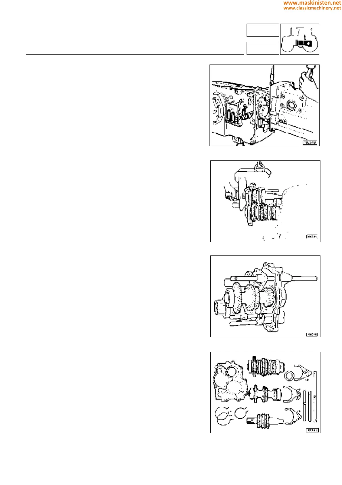
Stripping the gearbox
The three gearbox shafts are installed on a flange which also
serves as the front gearbox cover.
The whole assembly can be easily removed first loosening the
cover fixing screws and then withdrawing the whole unit making
use of a hoist, as shown in figure 21.
Prior to this operation, use a magnet to extract the pins securing
the control rods to the gearbox (on gearboxes equipped with
mini-reduction there are three such pins). See detail C in figure 44
on page 158).
To remove the shafts first disengage the rod forks loosening the
securing screws, then take the snap rings from inside the cover
seats and withdraw the shafts one after the other in sequence with
little movements which should not exceed 5 mm at a time.
The same procedure is to be performed in reversed order when
reassembling.
If one or more assembly components are to be replaced, it may
be necessary to replace the snap rings indicated in figure 28 with
new ones of the same type but having different thicknesses.
These should be inserted into seats freely without resulting in any
clearance in the part assembly.
The same instruction applies to the spacing washers contacting
the snap rings located either at the reverse gear unit shaft or the
secondary shaft end.
All washers must be fitted with their oil drain sections opposed to
the counterparts.
After assembly, on applying an axial load to the entire synchroni-
ser assembly, an end-float of 0.15-0.60 mm should be obtained
(a higher value indicates that the synchroniser is excessively worn
and therefore must be replaced).
Make sure that all parts are free to move and the engagement
occurs evenly.
Forks must be placed on the rods in such a way that they will not
rub against the synchronizer sleeve groove sides.
Fig. 20 - Separeting the gearbox .
Fig. 21 - Removing the whole gearbox assembly.
Fig. 22 - Gearbox assembly.
Fig. 23 - External controls detailed.
transmission
primary shaft - secondary shaft - reduction gear unit
3
32-33-34
149
www.maskinisten.net
www.classicmachinery.net