Mechanical controls
Given the constructional simplicity of these controls, a sequence of drawings is given here illustrating the single
component parts of each one.
Only certain of these require any adjustment, in which case reference is made to the chapter covering the assembly
with which the control is associated.
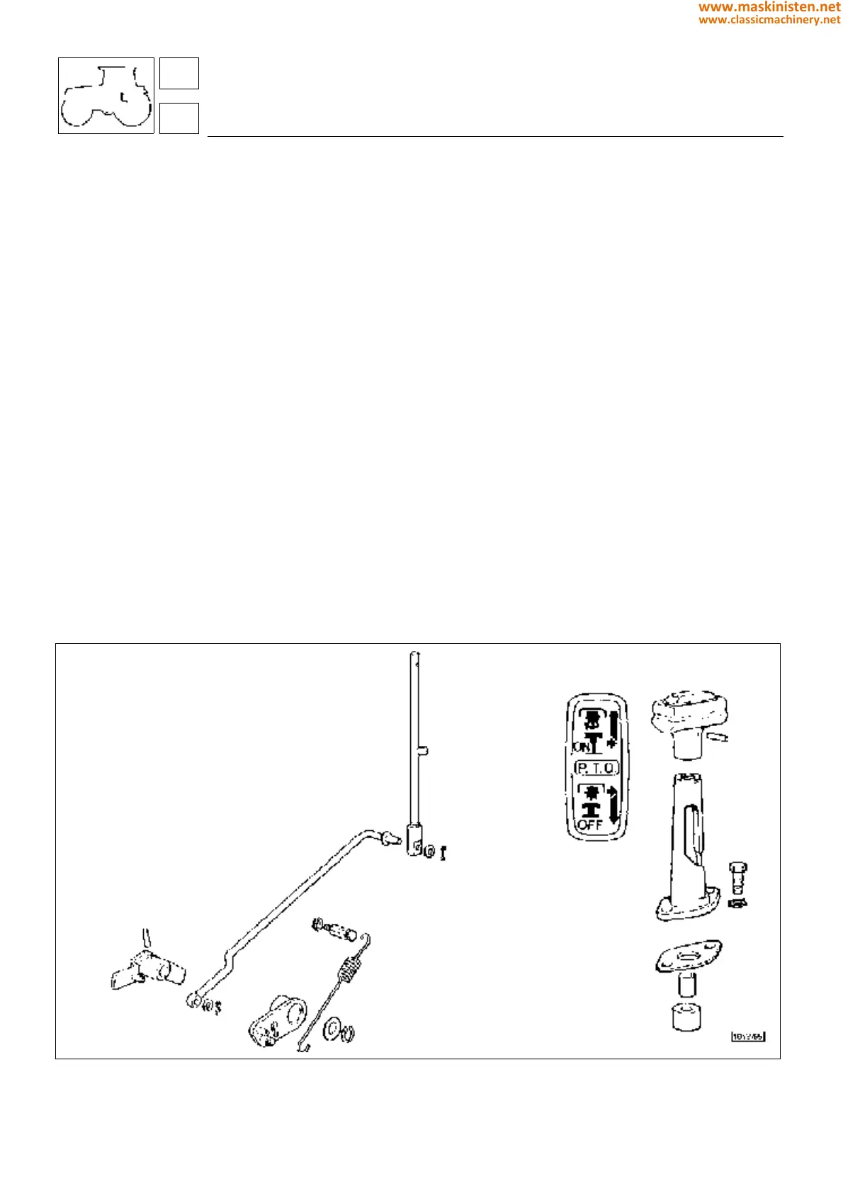
Fig 1 - Mechanically operated P.T.O. clutch
Fig 2 - Economy P.T.O. selector - external linkage
Fig 3 - Economy P.T.O. selector - internal linkage
Fig 4 - P.T.O. selector
Fig 5 - Live P.T.O. control linkages
Fig 6 - Four wheel drive selector
Fig 7 - Mechanically operated front differential lock
Fig 8 - Throttle control linkages
CAUTION: It is important that linkage rods with an adjustable clevis are adjusted in such a way that the associated
control levers can complete their full travel between maximum and minimum positions without impediment.
Fig. 1 - Mechanical operated P.T.O. clutch.
controls
mechanical controls
68
6
302
www.maskinisten.net
www.classicmachinery.net