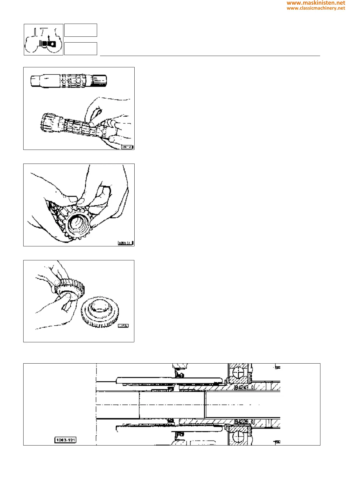
Fig. 24 - Checking the gearbox shafts removed.
Fig. 25 - Checking bushing for wear.
Fig. 26 - Checking gear teeth for wear.
Examining parts removed
Gearbox case
Gearbox case should show no cracks, bearing seats must not be worn
or damaged.
If seriuos damage or excessive wear is occured replace the parts con-
cerned.
Whenever the gearbox is disassembled clean all sealing surfaces remo-
ving old adhesive and applying some new on all surfaces evenly when
reassembling.
Shafts
Examine shafts for excessive wear and shaft splines for pitting, these
should allow the gears to slide freely.
Gears
Examine gear teeth for wear or damage and make sure these work on
the whole contact surface.
Check also the gear-mounted bushings for seizing: if so replace them.
Synchronizers
Check the ring inside tapered portion for excessive wear or damage and
be sure the gear part being frictioned by the synchronizer does not show
signs of scoring which may prevent the gear from meshing correctly.
To check the synchronizer ring for wear, measure the distance from the
friction cone; reading should be 1.25
−
0.15
+
0.30
mm with a new synchronizer
or drop to zero when the ring is maximally worn.
Bearings
Bearings should be in perfect conditions without showing excessive radial
or end play.
Holding the bearings pressed by hand and making them simultaneously
turn in both directions of rotation a free sliding as well as no roughness
at all should be felt.
Examine the taper roller bearings for proper working conditions, these
should be neither worn nor overheated, replace as soon as poor working
efficiency is suspected, as an abnormal bearing operation may result in
either gear tooth seizure or noisy gearbox.
Warning: oil leakages from the clutch-disk-to-gearbox shaft or the engi-
ne-flywheel-to-P.T.O.-clutch shaft may be stopped when the assembly
procedure is performed with the utmost care and operating in such a way
that the splined parts are prevented from damaging the O-ring and also
providing a thorough cleaning of the parts prior to being installed.
transmission
primary shaft - secondary shaft - reduction gear unit
3
32-33-34
Fig. 27 - Shafts from clutch plate to gearbox.
150
www.maskinisten.net
www.classicmachinery.net