The engine governor receives the speed signal in form of electric signal from a pick-up facing the engine flywheel ring
gear and controls the actuator installed on engine by an electronic control unit.
The control unit is fully digital type and contains the mode of operation defined for each engine model in form of
permanent storage programs (EPROM).
Communications towards the control unit may be entered by an EXTERNAL PROGRAMMER equipped with specific
functions enabling certain parameters to be diagnosed and set
.
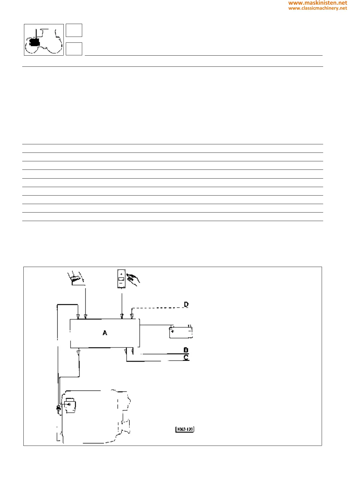
Fig. 25 - Configuration of the electronic engine control system.
A - ELECTRONIC CONTROL UNIT
B - DIAGNOSTICS
C - SPEED CONSUMPTION
D - PROGRAMMER
ELECTRONIC ENGINE GOVERNOR
General information
The electronic engine speed governor consisting of a REG2MK microprocessor permits an accurate and stable engine
r.p.m. control to be obtained. The system includes an ELECTRIC ACTUATOR, a MAGNETIC PICK-UP acting as a
speed recorder, a PUSH-BUTTON PANEL with LED indication (hand throttle) and a POTENTIOMETER located on the
accelerator pedal.
Specifications
power supply 8 to 15 V DC
card electrical input 35mA + actuator current
maximum actuator current output 6 A
PICK-UP input 5 to 30 Vrms
operating temperature range -40 to +85 °C
humidity rate 0 to 100% non condensed
control isochronous or with statism
speed range 600 to 2700 r.p.m.
overspeed set at 3500 r.p.m.
reliability 70 °C
engine
fuel system
16
1
64
www.maskinisten.net
www.classicmachinery.net