Engine r.p.m. governor operation:
Engine r.p.m. governor consists of the following parts:
— electronic control card on microprocessor;
— magnetic pick-up on engine flywheel;
— potentiometer on accelerator pedal;
— hand throttle push-button control panel and self-diagnosis
LEDs;
— magnetic actuator controlling the engine injection pump rack
rod.
The engine r.p.m. is selected by the operator through the accele-
rator pedal: the potentiometer connected to pedal supplies the
card 1 to 4 V voltage corresponding to a r.p.m. varying from
minimum to maximum r.p.m. available.
The magnetic pick-up located against the flywheel ring gear teeth
generates a voltage whose frequency is proportional to the engine
r.p.m.
The electronic control unit compares the engine r.p.m. from the
pick-up with the potentiometer reference thus setting up a current
in the actuator so that the desired engine r.p.m. may be estab-
lished.
The adjustment constants are preset in governor storage and for
this reason cannot be altered.
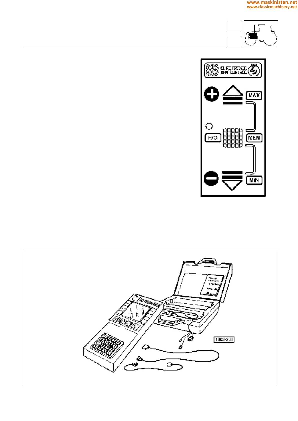
The push-button panel permits further adjusting functions to be
selected.
Three push buttons are provided in the push-button panel:
—UP
— HOLD/RESET
—DOWN
In addition, close to HOLD/RESET push button it is located a
special LED providing signalling and self-diagnosing functions.
NOTE: The hand throttle control forming part of the multifunction
type handset, incorporated into the seat armrest, is described in
the chapter devoted to the cab.
Fig. 26 - Electronic accelerator manual control.
Fig. 27 - Tester (SAT 5.9030.730.6) for checking the governor.
engine
fuel system
16
1
65
www.maskinisten.net
www.classicmachinery.net