Inspecting and checking brake assembly
Check the ground surfaces contacting the brake disks for exces-
sive scoring.
If excess wear is found replace the worn-out parts.
Check disk conditions and tickness, compare with specifications
table.
Examine the brake disk broaching for wear or damage.
If excessive oil consumption is noticed, check the piston rings as
follows:
Connect no. 5.9030.520.4 hydraulic pump to the oil delivery
circuit; if the hydraulic circuit is not fully oil-tight under a 1,5 bar
pressure, the rings must be replaced.
Perform a thorough check on each single brake.
Mark piston and brake housing case with a reference near to a
locating pin so as to make reassembly easier.
Coat the brake housing case seal ring contacting surfaces of
piston A with recommended grease, see figure 12.
Carefully mount piston into the brake housing case.
Fit the brake housings and halfshaft trumpet housings, repeating
the removal operations in reverse order and observing the fol-
lowing directions.
Coat the brake housing case inner surface as well as both epicy-
clic gear crown wheel surfaces with recommended sealant.
Tighten the securing nuts of the brake housings and trumpet
housings to the prescribed torque (see values below)
- brake housing bolts : 32÷40 Nm (3,3÷4,1 kgm);
- trumpet housing bolts: 84÷94 Nm (8,6÷9,6 kgm)
Adjusting service brake pedals
Operate right-hand pump fork A (figure 14) to adjust brake pedal
position, until the most suited position for the operator is attained,
and in such a way that the pedal may complete its whole travel
freely when braking.
Operate left-hand pump fork B (figure 14) to adjust the related
brake pedal so that the coupling latch holes are in the same line.
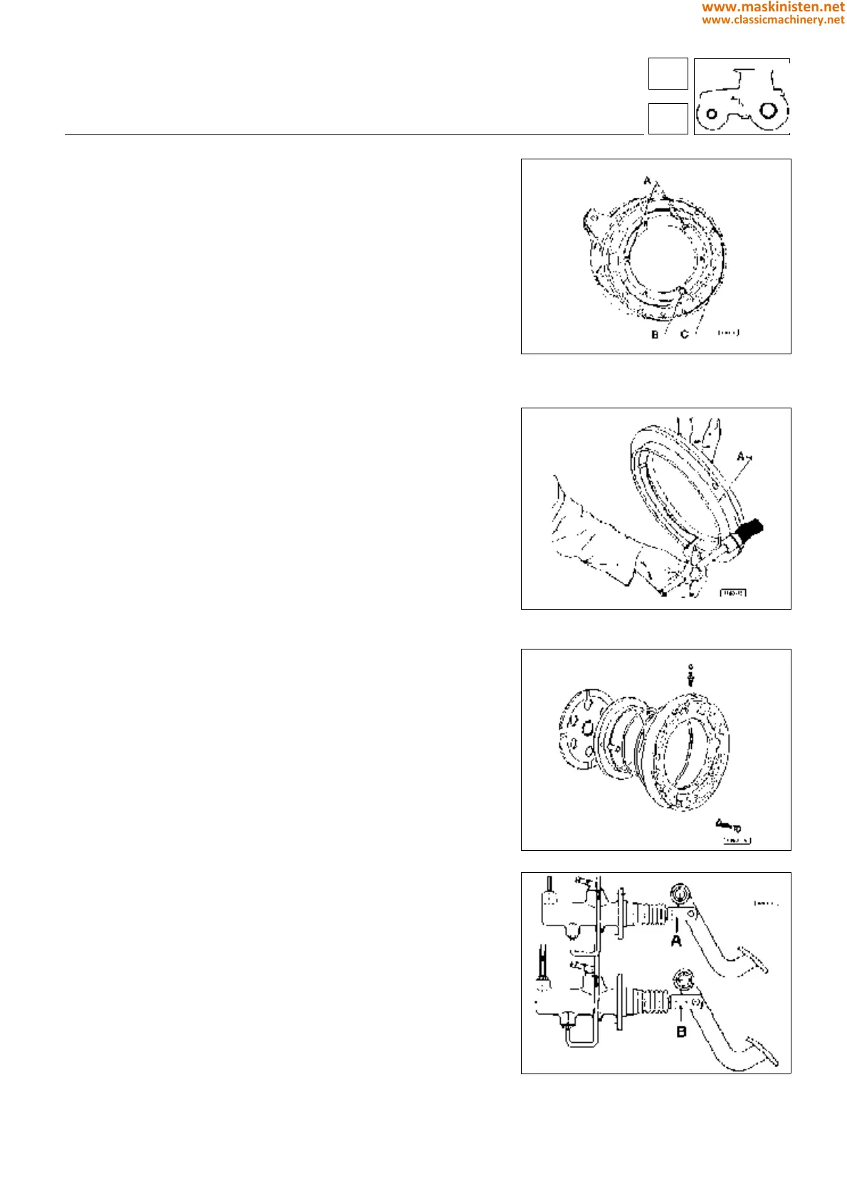
Fig. 11 - Brake housing case.
A - Locating pins
B - Brake housing case
Fig. 12 - Coating the piston surface in contact with
the seal ring with recommended grease.
A - Piston
Fig. 13 - Rear brake assembly
Fig. 14 - Adjusting service brake pedals.
vehicle
brakes
54
5
219
www.maskinisten.net
www.classicmachinery.net