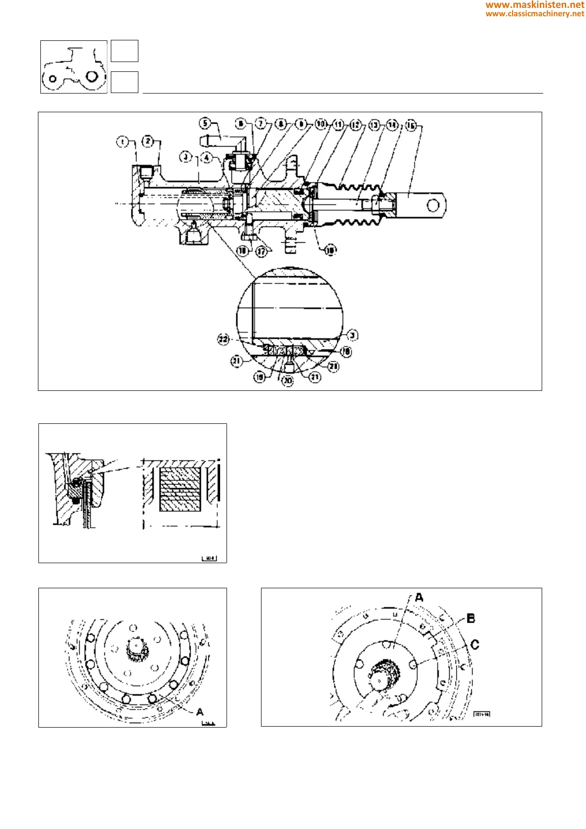
Fig. 7 - Cutaway view of the brake pump assembly.
Fig. 8 - Installing the front brake disk pressure
piston seal ring.
Fig. 9 - Brake assembly flange
A - Brake assembly flange
Assembly of brake master cylinder (see fig 5).
Screw the front piston L and the rear piston P together, then check
that there is clearance between the two.
Insert the pistons into the cylinder, checking that the recess
afforded by the outer piston P is aligned correctly with the seat of
the limiter screw X.
Verify correct operation of the cylinder, making certain that the
pistons complete their full travel freely.
Fig. 10 - Brake assembly.
A - Brake disks
B - Intermediate disk
C - Brake control piston
vehicle
brakes
12 Guard boot
13 Rod
14 Nut
15 Fork
16 Snap ring
17 Gasket
18 Stop screw
19 Seal ring
20 Seal ring
21 Spacer
22 Snap ring
1 Spring
2 Pump
3 Intermediate piston
4 Spring
5 Pipe fitting
6 Gasket
7 Seal ring
8 Washer
9 Piston
10 Seal ring
11 Support disk
54
5
218
www.maskinisten.net
www.classicmachinery.net