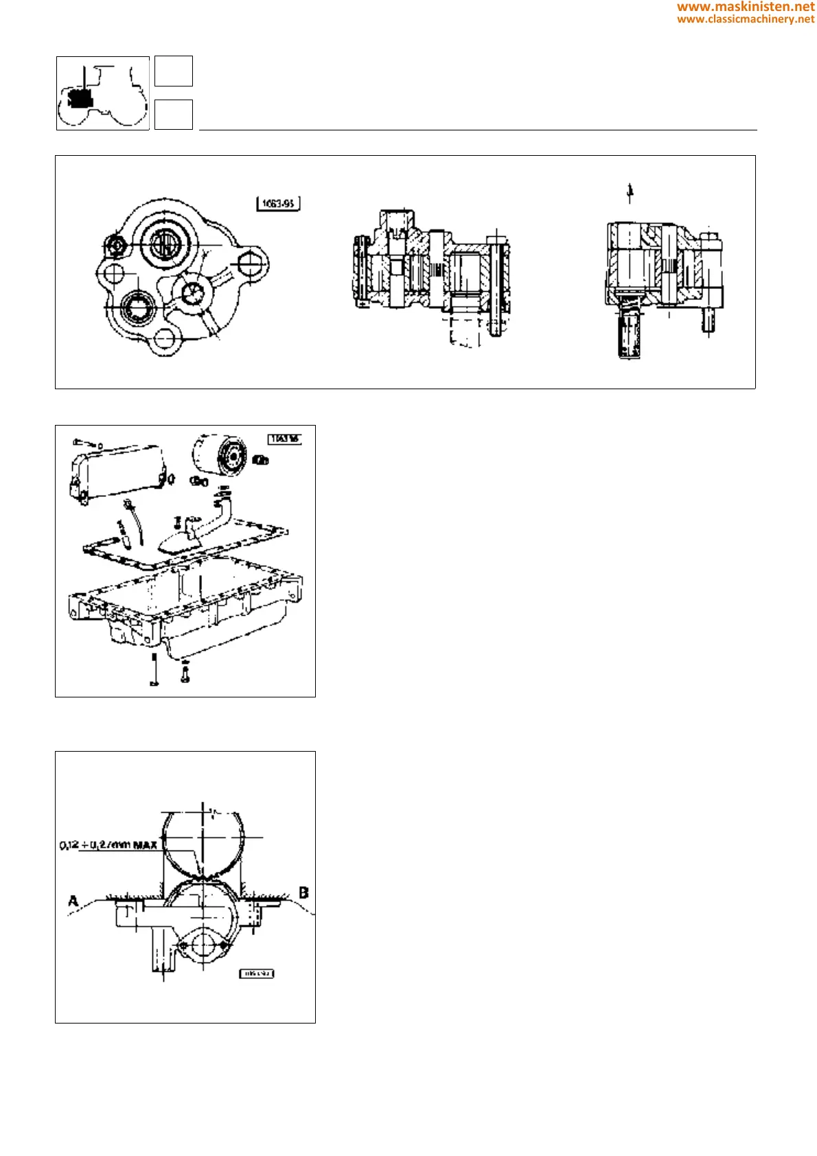
Fig. 2 - Oil radiator, oil filter and oil pan.
Fig. 3 - Oil pump -
SILVER 100.6
.
SILVER 80 - 90 - 100.4
Oil pump
Each time the oil pump is removed or installed, ensure the gears
can rotate freely and there is no evidence of tool spalling or wear.
Otherwise the whole pump assembly must be replaced.
To perform a complete oli pump efficiency test insert an oil flow
rate meter along with an oil pressure gauge between cylinder
block and oil filter. Ensure readings correspond to specifications
in page 18 table.
Checking pressure relief valve
Using the special fitting connect the valve to no. 5.9030.520.4
equipment and make sure the valve calibrating pressure is 4.9 to
5.9 bar. If this is not the case the valve should be replaced.
Warning: whenever the oil pan is removed, ensure the prefilter
wire mesh located under the oil rose pipe is thoroughly clean.
Engine oil pressure can also be checked on the special dash-
board-mounted indicator.
Engine oil level should never be below the minimum level notch
on dipstick.
SILVER 100.6
Shimming the engine oil pump
Between engine oil pump support and engine block fit the same
number of shims A - ref. code 007.0972.0 and B - ref. code
007.0973.0, so that the backlash between oil pump and crankshaft
gear teeth is 0.12 to 0.27 mm.
engine
lubrication system
Fig. 1 - Oil pump assembly cross-section -
SILVER 80 - 90 - 100.4.
15
1
50
www.maskinisten.net
www.classicmachinery.net