The installation of single-cylinder injection pumps besides ensur-
ing an even load distribution on the camshaft has permitted two
bearings per camshaft journal to be mounted in the engine block,
thus minimizing camshaft flexure.
A bimetallic bushing is inserted in each bearing to ensure very
smooth camshaft operation. This can be replaced when wear
exceeds the limits specified above.
All these features guarantee precise cam movement thus provid-
ing smooth timing system operation and regular fuel supply as
well.
The camshaft is held in position by a forked plate fitted on engine
front side.
For 1000.4-A engines
The engine oil pump and engine governor driving gear is mounted
at the rear camshaft end.
Prior to installing camshaft, the engine block should be turned
upside down and the tappets inserted in the related seats in the
block after having been properly lubricated with oil.
Make sure the tappets slide in their seats freely.
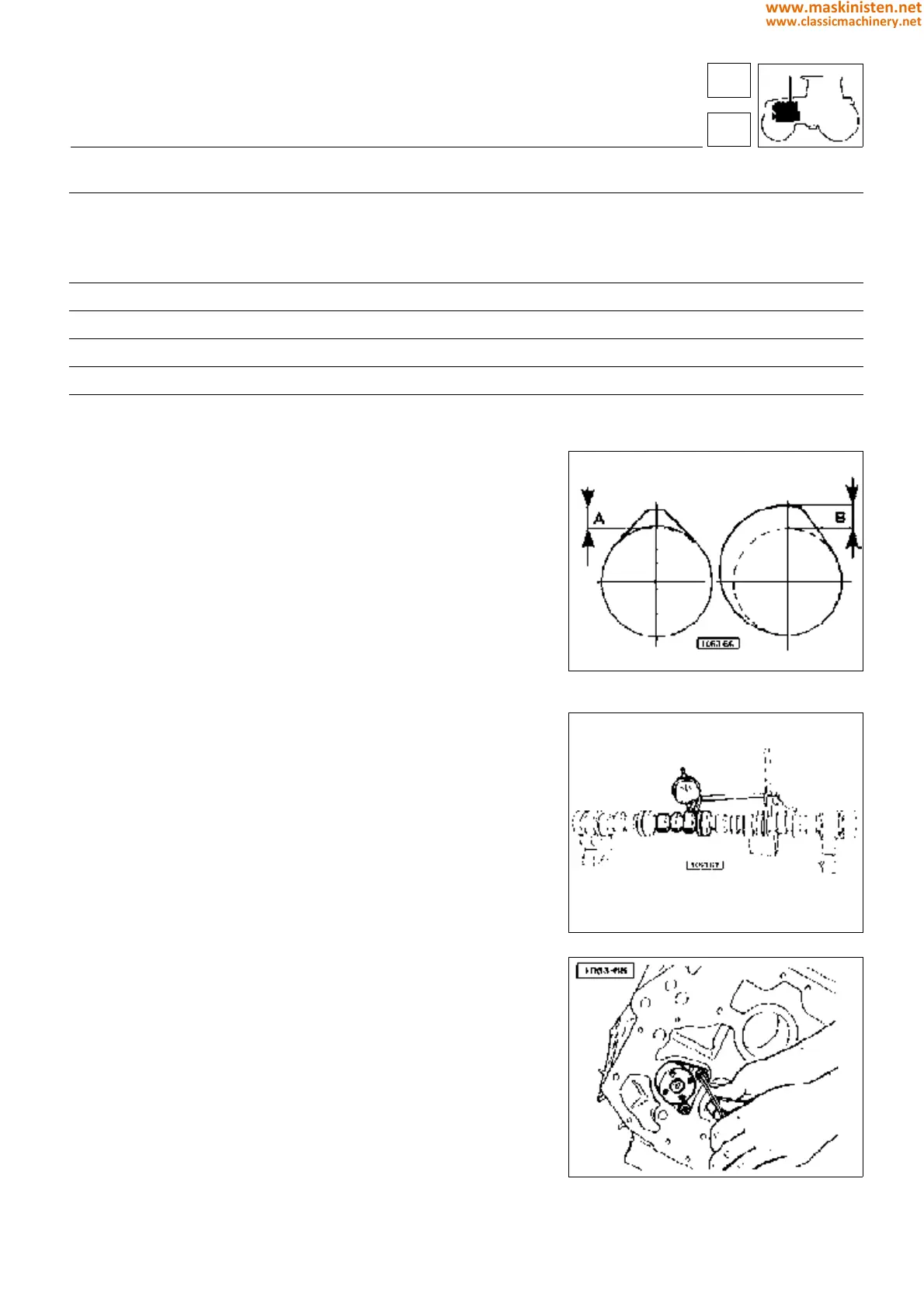
Fig. 1 - Timing system cams:
A - Valve cam; B - Injection cam.
Fig. 2 - Checking cam wear.
Fig. 3 - Camshaft fixing forked plate.
engine
camshaft
Ø machining Ø max. wear
Camshaft cam lift
intake cam mm 6,86
− 0,05
+ 0,05
6.30
exhaust cam mm 6,71
− 0.05
+ 0,05
6,20
injection cam mm 8
− 0,05
+ 0,05
7.50
Camshaft journal diameter mm 55
− 0,030
0
54.950
Camshaft bushing diameter mm 55
− 0,090
+ 0,060
55.180
Idler gear bushing diameter mm 40
− 0,064
+ 0,025
40.125
Idler gear pin diameter mm 40
− 0,025
0
39.950
13
1
43
www.maskinisten.net
www.classicmachinery.net