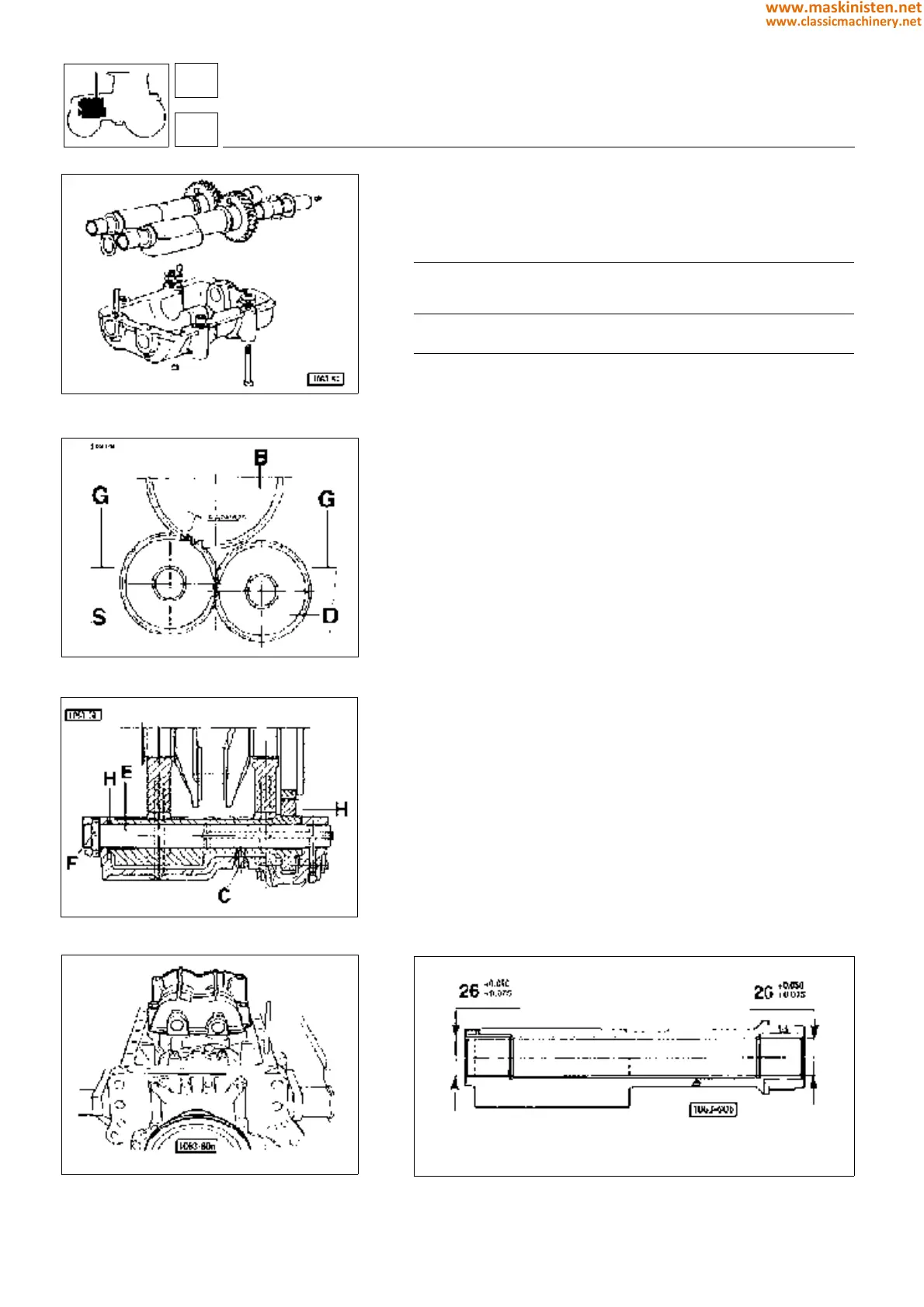
Fig. 37 - Counterweight assembly components.
Fig. 38 - Counterweight assembly.
Fig. 39 - Counterweight assembly cutaway-view.
Fig. 40 - Engine-installed counterweights.
Counterweights for 4-cylinder engines
Specifications
counterweight end play mm 0.10.43
backlash allowance
between counterweight and
crankshaft crown wheel teeth mm 0.200.25
bushing inside diameter mm 26
+ 0.075
+ 0.050
max. wear mm 26.150
Checking counterweights
Check counterweight bushing inside surface conditions. Ensure
the inside diameter is not above specifications; otherwise replace
bushings.
With bushing installed perform boring according to specifications
given in the table above.
Installing and adjusting counterweights
Position the weight marked with S in the related support seat, then
place weight D too, so that the engraved teeth coincide as shown
in figure.
Fit gudgeons E and insert spacer washers H.
Be sure the counterweight end play is 0.1 to 0.43 mm. Complete
installation by fixing gudgeons through special pins F and the
weights with securing screw C.
Apply the support and weight assembly underneath the cylinder
block so as the engraved counterweight S tooth engages between
the two engraved teeth of crankshaft crown wheel B. Then fit a
number of shims G until a 0.20 to 0.25 mm backlash between
crankshaft crown wheel and weight S teeth is obtained.
Remove screw C and finally tighten the weight support securing
screws to cylinder block also applying some Loctite 242.
Fig. 41 - Installed counterwight bushings.
engine
crankshaft
SILVER 80 - 90 - 100.4
12
1
40
www.maskinisten.net
www.classicmachinery.net