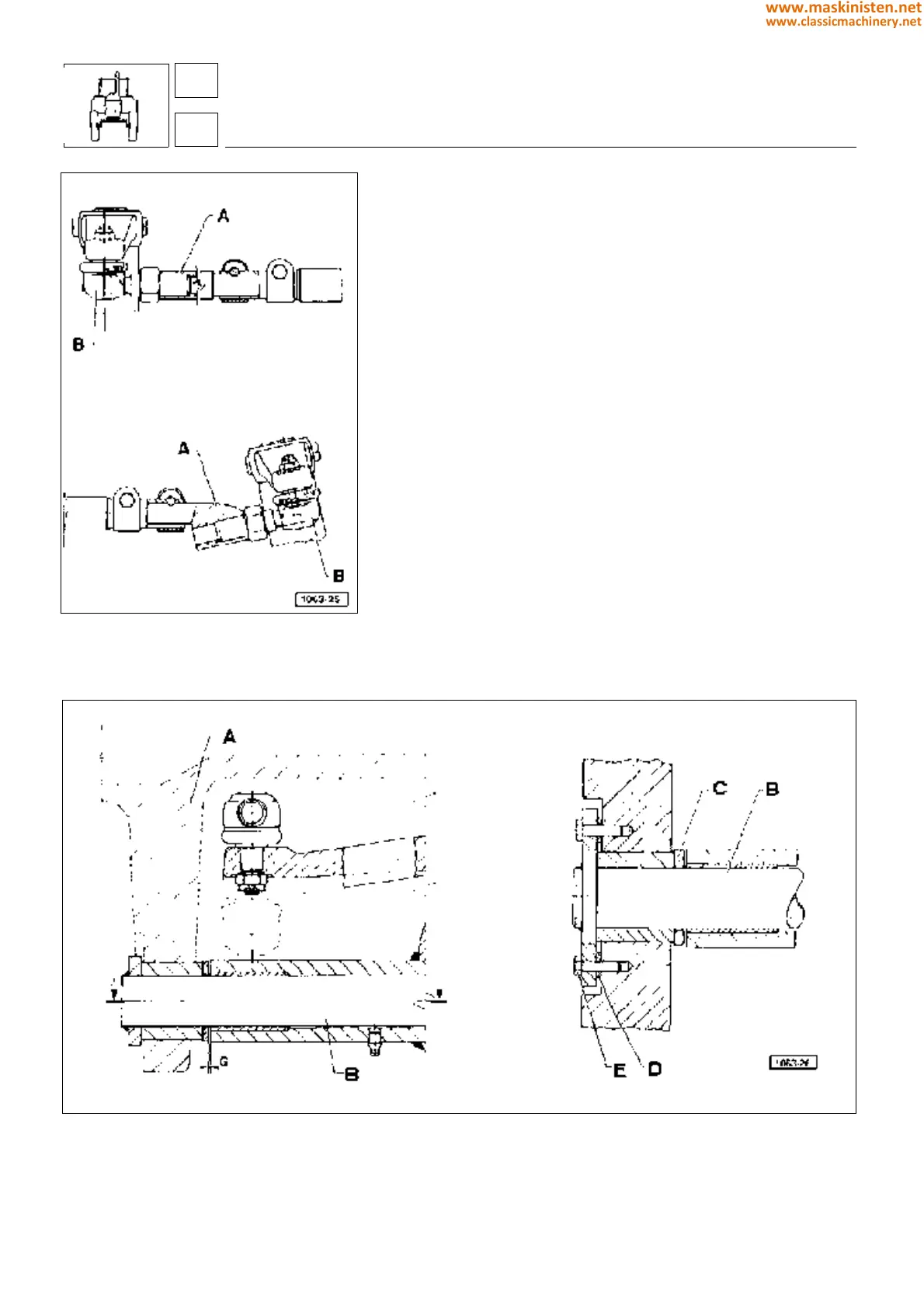
Fig. 25 - Steering linkage.
A - Sleeve
B - Steering knuckle
A - Front support
B - Pin
C - Shoulder ring
D - Shims
E - Screw
Correct steering rod assembly (Fig. 25)
Rotate sleeve A around its axis so that knuckle B attains the
position shown in figure, i.e. make sure the knuckle working angle
is 90°, then insert and tighten both sleeve securing bolts.
Adjusting end play (Fig. 26)
Push the axle backward and using a thickness gauge ensure
maximum play "G" is not above 0.4 mm.
If the reading exceeds specifications, operate as follows:
— Loosen screws E securing pin B to front support A.
— Slightly move the pin to take a number of shims D from
underneath the flange so that the correct play may be restored.
— Lock screws E and check play once again.
drive axles - axles
2-W.D. extendible axle
Fig. 26 - Adjusting the front axle end play.
42
4
194
www.maskinisten.net
www.classicmachinery.net