Using the following equipment:
5.9030.627.0 centesimal dial gauge
5.9030.433.0 dial gauge base
5.9030.631.4/10 cylinder pressing tool
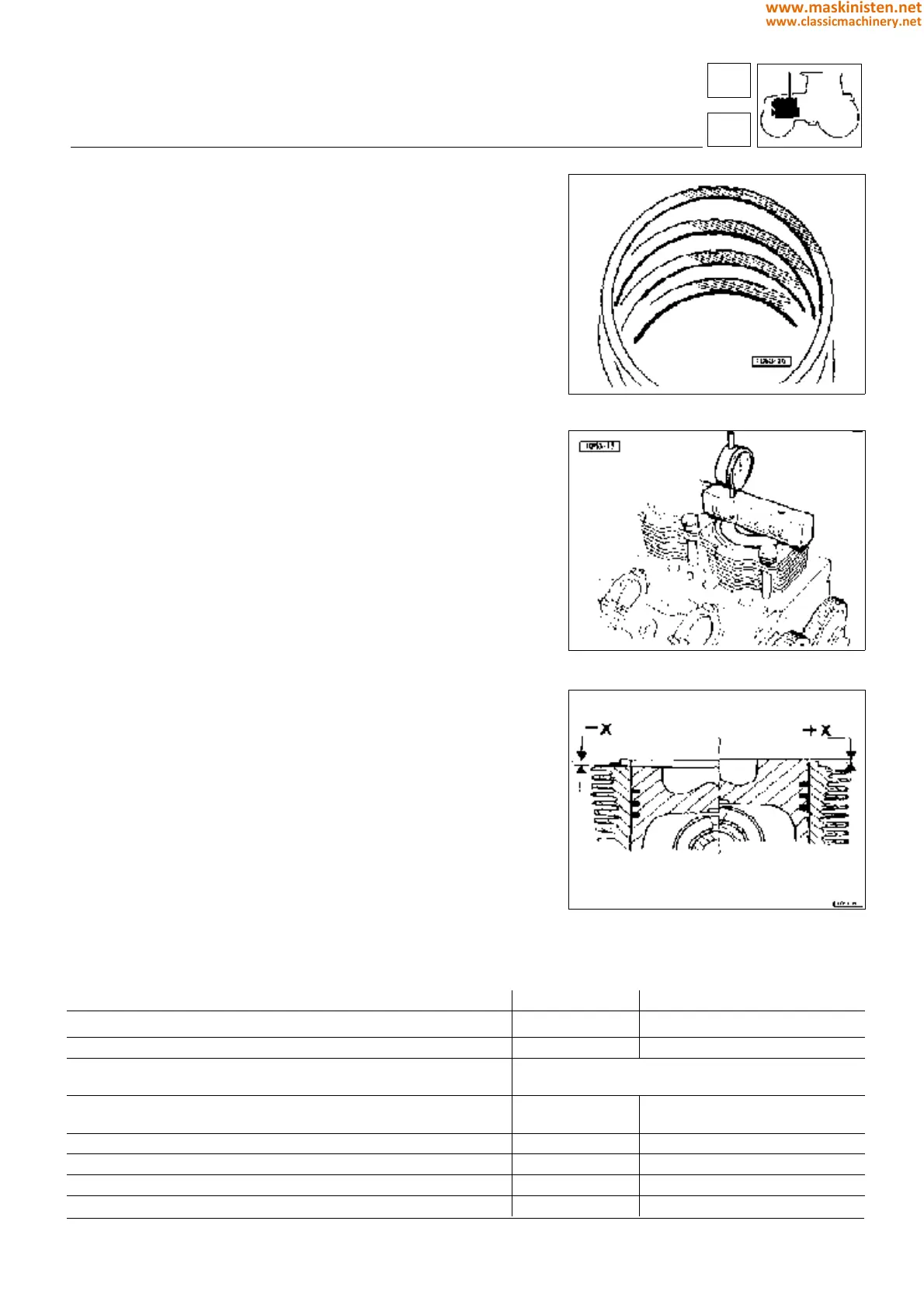
ensure the piston crown at T.D.C. recesses from the head gasket
bearing surface (see Fig. 6).
Move the dial gauge base until the gauge feeler lies on the cylinder
surface and take reading from the dial.
Reset the dial gauge.
Place the base so that the gauge feeler lies on the piston head at
T.D.C. and take reading.
Choose the gasket to be fitted according to reading taken (also
refer to item D in the table here below).
Fig. 5 - Cylinder head gasket.
Fig. 6 - Checking piston position at T.D.C.
Fig. 7 - Determining the engine cylinder head
gasket thickness.
engine
cylinders
Ø machining Ø max wear
A inside diameter measured half-way along the cylinder mm
105.000
+ 0,022
− 0
105.100
B roundness errormm 0.020 0.080
C piston recess from the head gasket
bearing face on cylinder mm
0.30÷0.40
D determination of head gasket thickness x
reading
gasket thickness
gasket ref. code 0.085.1450.0 mm -0.562 ÷ -0.300 0.5 without locating notches
gasket ref. code 0.085.1451.0 mm -0.290 ÷ -0.110 0.7 with 1 locating notch
gasket ref. code 0.085.1453.0 mm -0.100 ÷ +0.020 0.8 with 3 locating notches
gasket ref. code 0.085.1452.0 mm +0.030 ÷ +0.178 1 with 2 locating notches
12
1
27
www.maskinisten.net
www.classicmachinery.net