Having elevated the cab 10 to 20 cm, disconnect all wiring located under the platform and connected with
components mounted to the body, namely:
— lead connected to electronic lift draft control sensor (if fitted).
— lead connected to electronic lift position control sensor (if fitted).
— lead connected to fuel tank float.
— lead connected to hydraulic trailer brake control valve (if fitted).
— lead connected to engine pickup (machines with electronic rpm control system).
— lead connected to engine rpm sensor(machines with electronic rpm control system).
— lead connected to wheel speed sensor (machines with electronic lift system)
— lead connected to RADAR unit (if fitted).
— lead connected to electronic rpm control actuator.
Remove the cab.
CAUTION: make absolutely certain when lifting the cab that
all wiring, hoses and mechanical linkages have been dis-
connected, and that the structure separates without impedi-
ment from the tractor body.
IMPORTANT: If the fuel tank is also to be removed, discon-
nect the hose from the injection system return pipe.
Refitting the cab or platform
The cab is replaced by repeating the removal operations
described above, in reverse sequence.
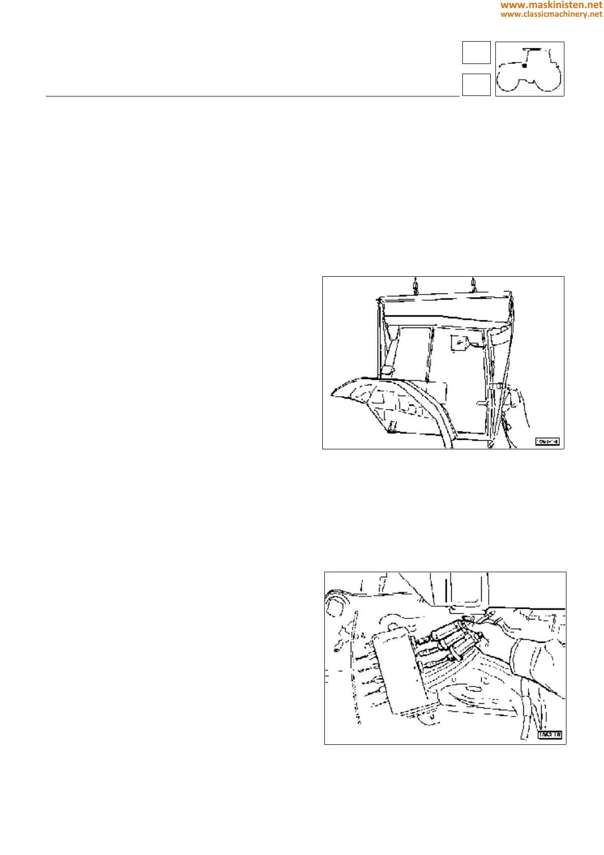
Bowden cables for auxiliary spool valves (see fig 35) are
best connected before repositioning the cab or platform on
the vehicle, as this will simplify operations.
body
driving position
Fig. 34 - Set the cab down on suitable blocks and proceed
with operations on the vehicle.
Fig. 35 - Connecting the auxiliary spool valve bowden cables
before refitting the cab to the tractor.
71
7
351
www.maskinisten.net
www.classicmachinery.net