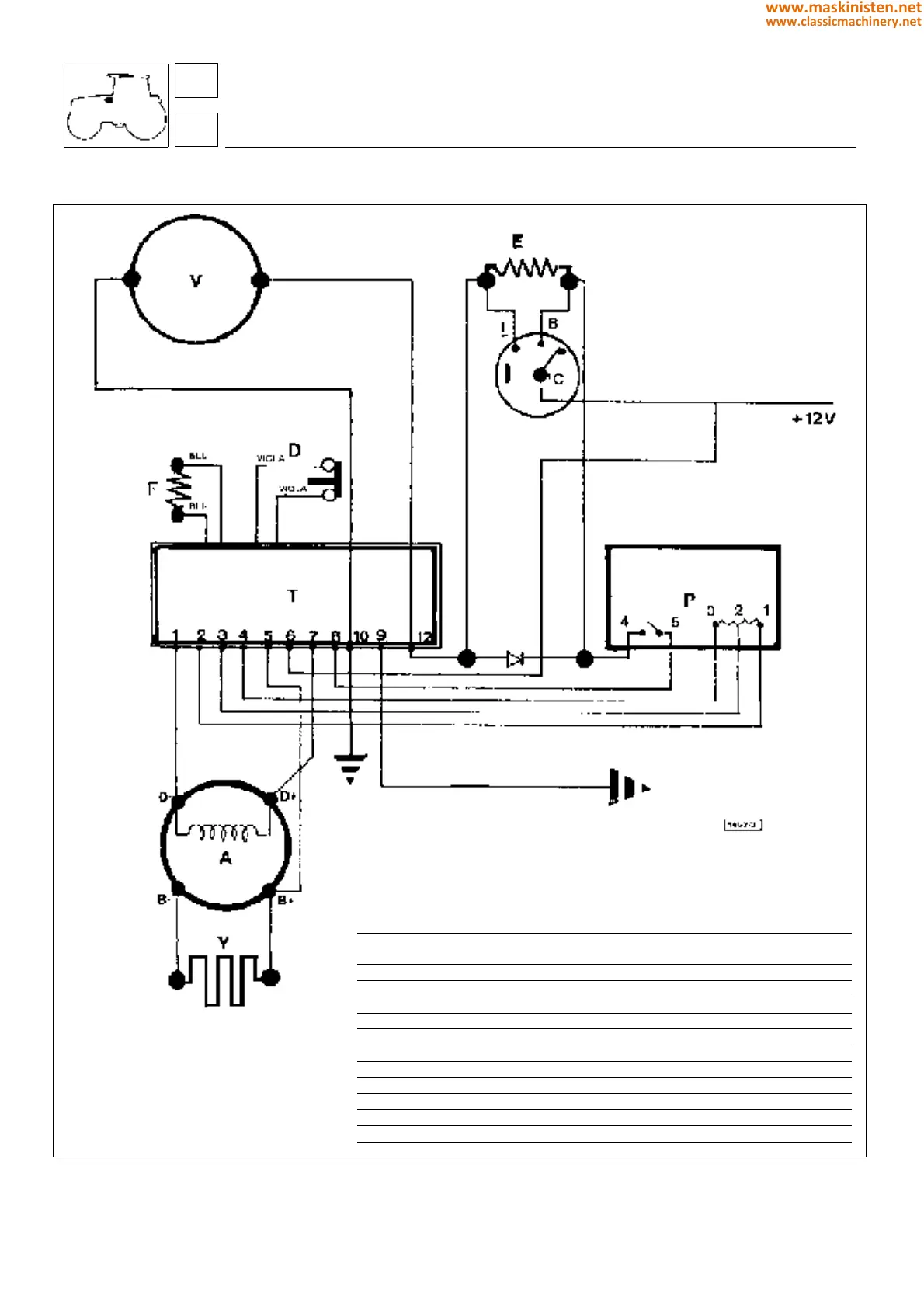
Electrical diagram - heating system
Fig. 3 - Electrical diagram - ventilation and heating system.
key
V Electric fan heater unit
E Fan heater element
I Fan heater switch
D Thermal overload cutout
T Electronic control unit
P Heater potentiometer
F Thermistor
A Alternator
Y Heater element
Ref Colour Symbol Section Length Function
(mm2) (cm)
1 Brown-black MN 1,5 50 Alternator field coil
2 Grey H 0,8 50 Full power
3 Orange C 0,8 60 Potentiometer slider
4 Green V 0,8 50 Potentiometer "0"
5 Yellow G 1,5 50 Potentiometer positive
6 Black-white BN 1,5 60 Speed switch
7 White B 1,5 60 Alternator field +
8 Blue-white AB 0,8 60 Potentiometer strength
9 Orange-black CN 0,8 70 Indicator lamp
10 Black N 2,5 60 Ground
12 Red-black RN 2,5 100 Motor +
systems
air conditioning
86
8
356
www.maskinisten.net
www.classicmachinery.net