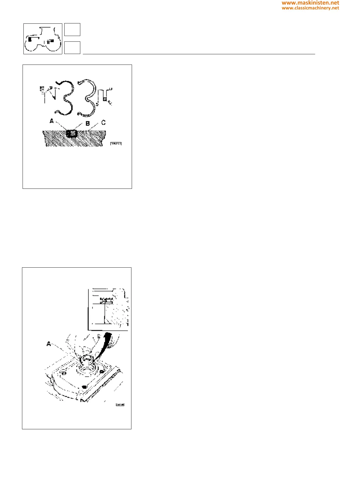
Fig. 9 - Inside seals.
Fig. 10 - Seal ring.
Inspections and checks
After removing all gaskets, both on the covers and in the pump
casing, carefully clean all parts using a proper solvent.
Carefully dry all parts with compressed air; this is to avoid that any
solvent residuals may damage the gaskets on reassembly.
Visually check the pump case internally and ascertain it is not
damaged.
Check both pinions and bearings for wear, abrasion due to foreign
matters or cavitation.
NOTE:
Should any damage, wear or in any case a component replace-
ment be required, with the exception of the gaskets, the entire
pump must be replaced.
WARNING:
Do not press onto the stop ring to prevent any damage.
Use a dial gauge to make sure the stop ring height be 2.1
− 0.15
+ 0.05
mm, otherwise replace taking care the new stop ring installed be
measured accordingly.
If reading is above specification fit the new ring in reversed position
and perform a grinding using a very fine emery cloth.
Assembly
Before assembly all parts shall be oiled.
Correctly position the gaskets in their seats paying particular attention
stop ring A and gasket B be correctly fitted into bearings C.
Coat the cover inner side with a slight grease layer then apply to
pump case and tightening the four securing screws to the recom-
mended torque.
WARNING:
The securing screws should be tightened gradually making also
sure that rotors are not hampered in their movements.
Tightening torques
Pump cover securing screws:
- M8 2 kgm (20 Nm)
- M10 5 kgm (49 Nm)
Restore the recommended oil level and then bleed the air from the
hydraulic circuit.
systems
hydraulic system
A - Seal ring
A - Stop ring
B - Gasket
C - Bearings
82
8
380
www.maskinisten.net
www.classicmachinery.net