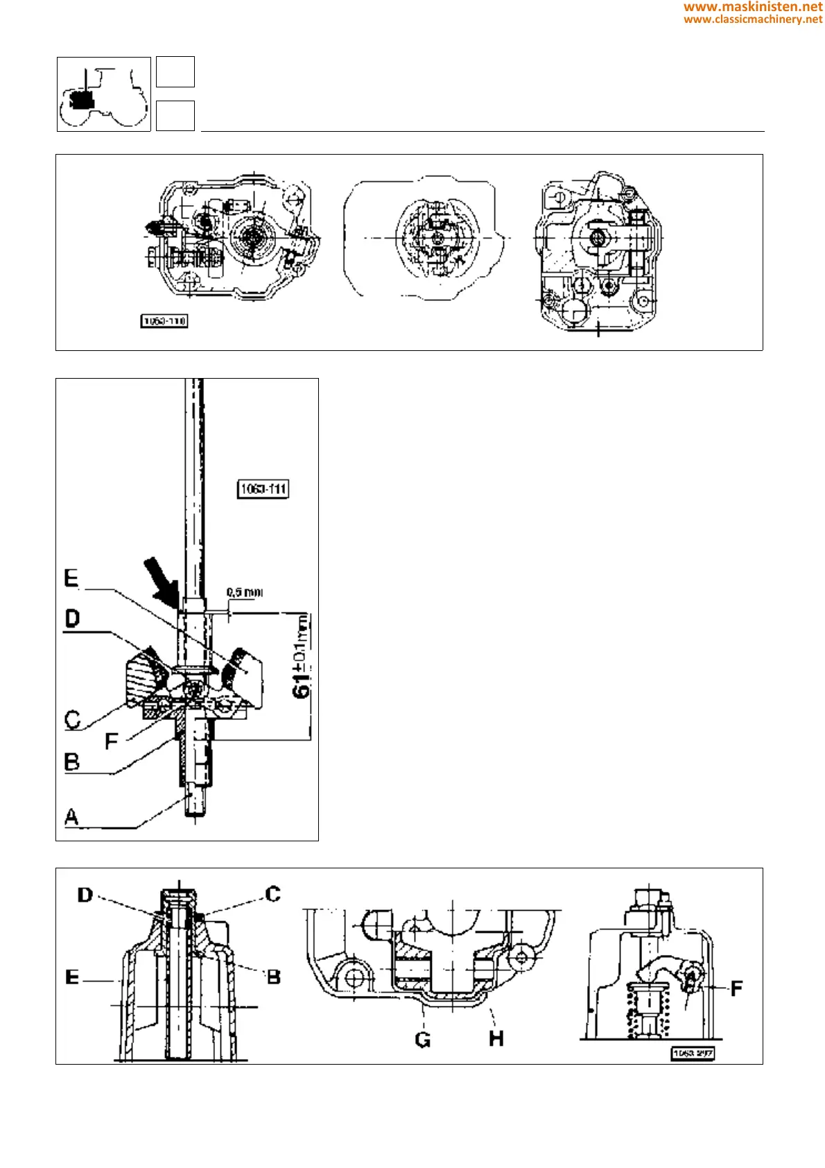
Fig. 11 - Installing weights on the governor shaft.
Mounting governor weights (Fig. 11)
Apply Loctite 601 to the crankshaft surface A in contact with
support B, then fit the support to the crankshaft, positioning the
two pieces to allow fitting of dowel F. Fit the weights C and E to
the support by means of plates D inserted in the groove of the
sliding sleeve.
Open weight C against the stop thereby holding the weight whose
plate rests on the coupling and releasing the other one, then move
the coupling against the locked plate. Be sure the dimension
reading is 61
±
0.1 mm, as shown in Fig. 11, otherwise add or
remove shims (ref. code 2.1589.160.0 and 2.1589.161.0) to/from
the position indicated by the arrow.
Installing governor assembly
Lower casing
Install the engine STOP control levers, both internal and external
ones, then insert the plate and related stop screws (see items a
in fig. 14).
Place bearing A (fig. 13) into the casing and fit levers B and C (fig.
13) along with the full assembly components (b fig. 14).
Warning: Before installing lever C be sure this has a 20 mm
portion showing absolutely no indentation (see figure 13).
Install the shaft and mounted weights securing to the bearing with
the special nut.
Install bearing D as well as the sliding coupling and fit the eccentric
screw E into the casing, paying attention the chiseling on the screw
head is in the upper position.
Fig. 10 - Engine governor assembly cross-section.
engine
fuel system
SILVER 80 - 90 - 100.4 - 100.6
Fig. 12 - Governor sealing points with LOCTITE.
16
1
56
www.maskinisten.net
www.classicmachinery.net