Full-load fuel delivery governor operation depen-
ding on turbocharging pressure
L.D.A. valve
(Ladedruckabhängiger Vollastanschlag - Full-
load fuel delivery stop valve)
NOTE: Before adjusting the L.D.A. valve it is first required the
governor calibration be carried out.
This calibration should be performed after locking the L.D.A. valve
as follows:
— loosen nut O and screw in screw N until plate G is contacting
the valve casing.
— after calibration is ended loosen screw N of 2.1/4 turns and lock
the nut.
As regards governor calibration follow the procedure referred to
on previous page.
No. of turns of the governor calibrating rod adjusting screw: 10 (10
mm).
L.D.A. valve adjustment
To be performed only in the event of valve stripping with governor
removed from engine. The injection pump rod control lever should
not be constrained.
Do not loosen the two screws securing the valve casing to the
governor, should it be necessary first mark their positions so that
on reassembly an equal amount of shimming washers may be
fitted in the same positions.
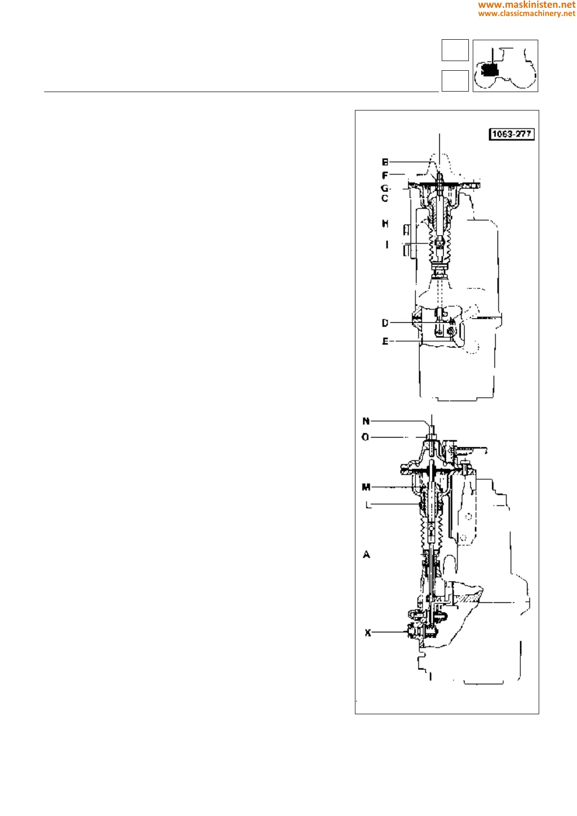
After removing the L.D.A. valve cover, unscrew nut F, remove the
underlying diaphragm and spring; then rotate nut C a few turns
and install diaphragm again. Pull tie rod B upwards until feeling
the contact between pin D and lever E.
Screw on nut F until bringing plate G against the valve casing.
Remove guard H from the top and lower downward, then remove
pin I and withdraw tie rod B from top.
Screw nut C against plate G and afterwards unscrew by half a
turn.
Holding nut C in position tighten nut F, loosen ring nut L and place
bushing M against the valve casing face, then unscrew by 3/4 turn.
Lock ring nut L, install spring and tie rod B.
Adjusting L.D.A. valve operating stroke
After installing L.D.A. valve cover drive screw N until plate G
contacts the valve casing, then loosen screw by 2.1/4 turns and
finally lock with nut O.
Fig. 17 - L.D.A. valve adjustment.
SILVER 100.4
engine
SILVER 100.4
fuel system
16
1
59
www.maskinisten.net
www.classicmachinery.net