Installing and checking actuator
When installing the actuator take note of the following:
— the actuator lever should move the pump rod freely and without friction;
— a free rod must return in stop position;
— the actuator rod must be matched to the pump rod fork with a slight play.
WARNING:
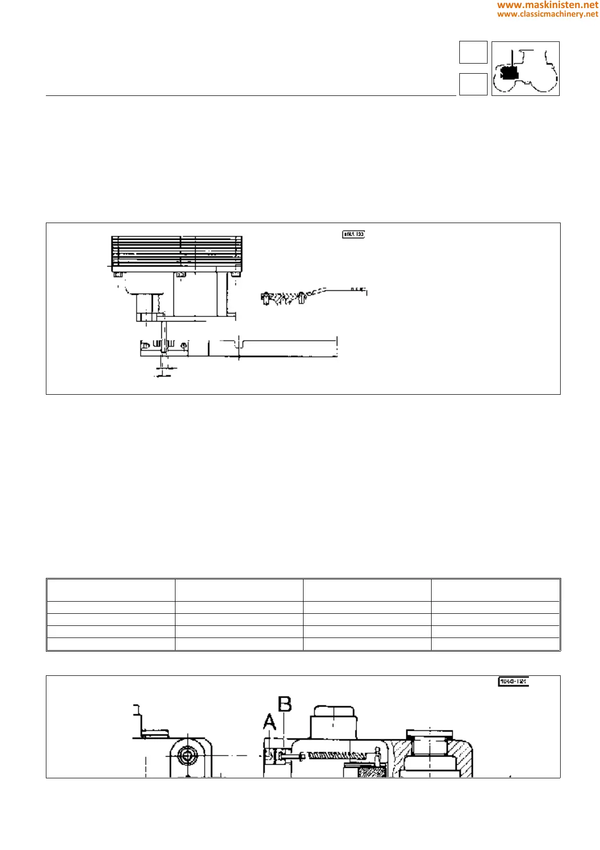
The actuator is provided with cover A (Fig. 28) to protect the access to the injection pump control rod stroke adjusting
device.
This cover is secured to the actuator by means of self-tapping rivet B (Fig. 28).
Fig. 30 - Positioning the injection pumps actuator and control rod clevis.
Calibrating the governor actuator
Calibrating the actuator is a most delicate operation.
This should be performed in case of external interventions including actuator replacement.
Operate as follows:
— Turn on the engine and run to 2000
±
100 r.p.m. using the hand throttle.
The engine should never be subjected to dragging loads, make sure the red LED on hand throttle control lever is
illuminated.
— Remove plug A (Fig. 31) to gain access to the actuator spring for spring load setting and loosen screw B (Fig. 31)
until first the engine r.p.m. droops and then the engine stops.
WARNING: locating this condition requires most accuracy and meticulous operating procedure and namely:
— locate approximately the point where the engine r.p.m. starts drooping;
— with engine stationary lock the screw B (Fig. 31) of a number of turns as shown in table below.
Fig. 31 - Setting the rpm control actuator.
Calibration on a specific test bench:
power supply 2A
±
0,01
rod stroke 11,5
+ 0,2
mm
TRACTOR TYPE ENGINE R.P.M. HP
ADJUSTING SCREW B
TIGTHENING TURN NO.
SILVER 80 2100 80 3,75
SILVER 90 2100 90 3,25
SILVER 100.4 2100 100.4 4,75
SILVER 100.6 2100 100.6 3
CAUTION: When fitting plug A operate so as any alteration of the adjusting screw B position may be prevented.
engine
fuel system
16
1
67
www.maskinisten.net
www.classicmachinery.net