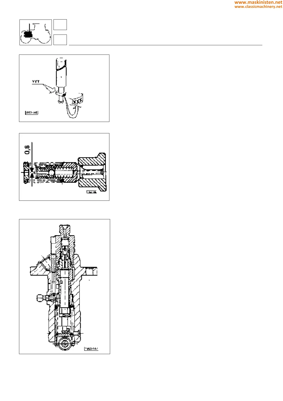
Fig. 11 - Injection pump plunger identification
marks.
Fig. 12 - Injection pump G.D.V. valve.
Fig. 13 - Injection pump section 2.4619.050.0/20.
Positioning the pumps (fig. 10).
Before positioning the pumps, lock the control rod using tool
5.9030.728.0, which is to be positioned with the governor removed
and as shown in figure 10.
Then position each injection pump (interposing a shim pack of the
predetermined thickness), so that the dog engages the fork in the
control rod.
Rotate the pump clockwise until you feel the dog fully engage the
fork, then tighten the retaining screw.
NB: The pump must be positioned with the injection cams in b.d.c.
position.
Remove tool (B Fig. 10), release the pump by removing the lock
pin A (Fig. 10); fit the governor and the rear plug (flywheel end).
Check that the rod moves freely and that the STOP control
operates correctly.
Servicing
All the pumps are interchangeable as all the plungers are of the
same type.
N.B: new plungers can be identified from the markings in the
positions shown in figure 11.
Removal and refitting of an injection pump without replacing
components.
This operation does not require the use of any special tools. Refit
the pump using a shim pack of the original thickness.
Hold the pump control rack in position using lock pin A (fig. 10) to.
To do this, operate the STOP control lever so that the pin engages
the relative notch on the pump control rod rack.
Install the pump (also equipped with a rack lock pin) in the cylinder
block, making sure that the dog engages in the fork of the control
rod; then rotate the pump in a clockwise direction whilst simulta-
neously pushing the control rod through the engine inspection
flange towards the front of the engine.
Removal and refitting of a pump after replacing one or more
components
Before installation the pump must be re-calibrated on a test bench.
Remove any previous timing marks and stamp a new notch and
dimension (Y) on the pump.
Refit the pump using a shim pack (see fig. 16) according to the
new dimension stamped on the pump (always make a note of the
old value stamped on the pump before erasure, in order to facilitate
calculation of the new shim pack thickness) and follow the instruc-
tions given in the previous point.
Replacing a pump
The thickness of the shim pack (X +Y) must be corrected by first
removing shims to the thickness
indicated on the previous pump and then adding shims to the value
indicated on the new pump.
engine
fuel system
16
1
78
www.maskinisten.net
www.classicmachinery.net