SAMSUNG Installation
DCS-816 February, 1999
2-7
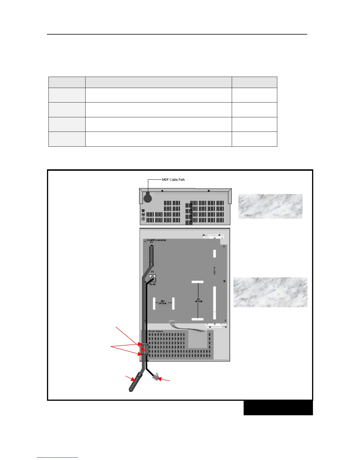
Details of the RJ-45 connections
Eight pins of the RJ-45 connector are assigned to connections of SLT interface ports on the base
board.
Pin No. Circuits/ Functions Remarks
1
8
Tip, 1
st
SLT port (STN 13) on the base board
Ring, 1
st
SLT port (STN 13) on the base board
No polarity
2
7
Tip, 2
nd
SLT port (STN 14) on the base board
Ring, 2
nd
SLT port (STN 14) on the base board
No polarity
3
6
Tip, 3
rd
SLT port (STN 15) on the base board
Ring, 3
rd
SLT port (STN 15) on the base board
No polarity
4
5
Tip, 4
th
SLT port (STN 16) on the base board
Ring, 4
th
SLT port (STN 16) on the base board
No polarity